

218 Earthquakes
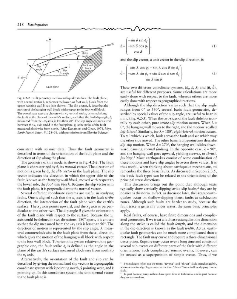
Fig. 4.2-2 Fault geometry used in earthquake studies. The fault plane,
with normal vector 4, separates the lower, or foot wall, block from the
upper hanging wall block (not shown). The slip vector, 2, describes the
motion of the hanging wall block with respect to the foot wall block.
The coordinate axes are chosen with x 3 vertical and x 1 oriented along
the fault in the plane of the earth’s surface, such that the fault dip angle, δ,
measured from the −x 2 axis, is less than 90°. The slip angle λ is measured
between the x 1 axis and 2 in the fault plane. φ f is the strike of the fault
measured clockwise from north. (After Kanamori and Cipar, 1974. Phys.
Earth Planet. Inter., 9, 128–36, with permission from Elsevier Science.)
4 =
−
−
⎛
⎝
⎜
⎜
⎜
⎞
⎠
⎟
⎟
⎟
sin sin
sin cos
cos
,
δ
φ
δ
φ
δ
f
f
(1)
and the slip vector, a unit vector in the slip direction, is
2 =
cos cos
sin cos sin
cos sin
sin cos cos
sin sin
.
λ
φ
λ
δ
φ
λ
φ
λ
δ
φ
λ
δ
f
f
f
f
+
−
+
⎛
⎝
⎜
⎜
⎜
⎞
⎠
⎟
⎟
⎟
(2)
These two different coordinate systems, (φ f , δ, λ) and (4, 2),
are useful for different purposes. Some calculations are more
easily done with respect to the fault, whereas others are more
easily done with respect to geographic directions.
Although the slip direction varies such that the slip angle
ranges from 0° to 360°, several basic fault geometries, described by special values of the slip angle, are useful to bear in
mind (Fig. 4.2-3). When the two sides of the fault slide horizontally by each other, pure strike-slip motion occurs. When λ =
0°, the hanging wall moves to the right, and the motion is called
left-lateral. Similarly, for λ = 180°, right-lateral motion occurs.
To tell which is which, look across the fault and see which way
the other side moved. The other basic fault geometries describe
dip-slip motion. When λ = 270°, the hanging wall slides downward, causing normal faulting. In the opposite case, λ = 90°,
and the hanging wall goes upward, yielding reverse, or thrust,
faulting. 1 Most earthquakes consist of some combination of
these motions and have slip angles between these values. It is
thus useful, when thinking about earthquake mechanisms, to
remember the three basic faults. As discussed in Section 2.3.5,
the basic fault types can be related to the orientations of the
principal stress directions.
This discussion brings out the point that although texts
typically show vertically dipping strike-slip faults, 2 they are by
no means the norm. In fact, as discussed later, the largest earthquakes occur on shallow-dipping thrust faults at subduction
zones. Although such faults are harder to study, because the
fault trace is generally under water, the same basic principles
apply.
Real faults, of course, have finite dimensions and complicated geometries. If we treat a fault as rectangular, the dimension
along the strike is called the fault length, and the dimension
in the dip direction is known as the fault width. Actual earthquake fault geometries can be much more complicated than a
rectangle. The fault may curve and require a three-dimensional
description. Rupture may occur over a long time and consist of
several sub-events on different parts of the fault with different
orientations. Such complicated seismic events, however, can
be treated as a superposition of simple events. Thus, if we
1 Seismologists often use the terms “reverse” and “thrust” fault interchangeably,
whereas structural geologists reserve the term “thrust” for a shallow-dipping reverse
fault.
2 In part because many authors have spent time in California, and in part because
they are easy to draw.
Fault plane
Slip
angle
Foot wall
block
N o rt h
Strike
angle
x 2
x 3
x 1
Dip
angle
ˆ
n ⋅ ˆ
d = 0
δ
λ
ˆ
d
φ f
ˆ
n
consistent with seismic data. Thus the fault geometry is
described in terms of the orientation of the fault plane and the
direction of slip along the plane.
The geometry of this model is shown in Fig. 4.2-2. The fault
plane is characterized by 4, its normal vector. The direction of
motion is given by 2, the slip vector in the fault plane. The slip
vector indicates the direction in which the upper side of the
fault, known as the hanging wall block, moved with respect to
the lower side, the foot wall block. Because the slip vector is in
the fault plane, it is perpendicular to the normal vector.
Several different coordinate systems are useful in studying
faults. One is aligned such that the x 1 axis is in the fault strike
direction, the intersection of the fault plane with the earth’s
surface. The x 3 axis points upward, and the x 2 axis is perpendicular to the other two. The dip angle δ gives the orientation
of the fault plane with respect to the surface. Because the x 1
axis could be defined in two directions, 180° apart, it is chosen
so that the dip measured from the –x 2 axis is less than 90°. The
direction of motion is represented by the slip angle, λ, measured counterclockwise in the fault plane from the x 1 direction,
which gives the motion of the hanging wall block with respect
to the foot wall block. To orient this system relative to the geographic one, the fault strike φ f is defined as the angle in the
plane of the earth’s surface measured clockwise from north to
the x 1 axis.
Alternatively, the orientation of the fault and slip can be
described by giving the normal and slip vectors in a geographic
coordinate system with 7 pointing north, 8 pointing west, and 9
pointing up. In this coordinate system, the unit normal vector
to the fault plane is
Fig. 4.2-2 Fault geometry used in earthquake studies. The fault plane,
with normal vector 4, separates the lower, or foot wall, block from the
upper hanging wall block (not shown). The slip vector, 2, describes the
motion of the hanging wall block with respect to the foot wall block.
The coordinate axes are chosen with x 3 vertical and x 1 oriented along
the fault in the plane of the earth’s surface, such that the fault dip angle, δ,
measured from the −x 2 axis, is less than 90°. The slip angle λ is measured
between the x 1 axis and 2 in the fault plane. φ f is the strike of the fault
measured clockwise from north. (After Kanamori and Cipar, 1974. Phys.
Earth Planet. Inter., 9, 128–36, with permission from Elsevier Science.)
4 =
−
−
⎛
⎝
⎜
⎜
⎜
⎞
⎠
⎟
⎟
⎟
sin sin
sin cos
cos
,
δ
φ
δ
φ
δ
f
f
(1)
and the slip vector, a unit vector in the slip direction, is
2 =
cos cos
sin cos sin
cos sin
sin cos cos
sin sin
.
λ
φ
λ
δ
φ
λ
φ
λ
δ
φ
λ
δ
f
f
f
f
+
−
+
⎛
⎝
⎜
⎜
⎜
⎞
⎠
⎟
⎟
⎟
(2)
These two different coordinate systems, (φ f , δ, λ) and (4, 2),
are useful for different purposes. Some calculations are more
easily done with respect to the fault, whereas others are more
easily done with respect to geographic directions.
Although the slip direction varies such that the slip angle
ranges from 0° to 360°, several basic fault geometries, described by special values of the slip angle, are useful to bear in
mind (Fig. 4.2-3). When the two sides of the fault slide horizontally by each other, pure strike-slip motion occurs. When λ =
0°, the hanging wall moves to the right, and the motion is called
left-lateral. Similarly, for λ = 180°, right-lateral motion occurs.
To tell which is which, look across the fault and see which way
the other side moved. The other basic fault geometries describe
dip-slip motion. When λ = 270°, the hanging wall slides downward, causing normal faulting. In the opposite case, λ = 90°,
and the hanging wall goes upward, yielding reverse, or thrust,
faulting. 1 Most earthquakes consist of some combination of
these motions and have slip angles between these values. It is
thus useful, when thinking about earthquake mechanisms, to
remember the three basic faults. As discussed in Section 2.3.5,
the basic fault types can be related to the orientations of the
principal stress directions.
This discussion brings out the point that although texts
typically show vertically dipping strike-slip faults, 2 they are by
no means the norm. In fact, as discussed later, the largest earthquakes occur on shallow-dipping thrust faults at subduction
zones. Although such faults are harder to study, because the
fault trace is generally under water, the same basic principles
apply.
Real faults, of course, have finite dimensions and complicated geometries. If we treat a fault as rectangular, the dimension
along the strike is called the fault length, and the dimension
in the dip direction is known as the fault width. Actual earthquake fault geometries can be much more complicated than a
rectangle. The fault may curve and require a three-dimensional
description. Rupture may occur over a long time and consist of
several sub-events on different parts of the fault with different
orientations. Such complicated seismic events, however, can
be treated as a superposition of simple events. Thus, if we
1 Seismologists often use the terms “reverse” and “thrust” fault interchangeably,
whereas structural geologists reserve the term “thrust” for a shallow-dipping reverse
fault.
2 In part because many authors have spent time in California, and in part because
they are easy to draw.
Fault plane
Slip
angle
Foot wall
block
N o rt h
Strike
angle
x 2
x 3
x 1
Dip
angle
ˆ
n ⋅ ˆ
d = 0
δ
λ
ˆ
d
φ f
ˆ
n
consistent with seismic data. Thus the fault geometry is
described in terms of the orientation of the fault plane and the
direction of slip along the plane.
The geometry of this model is shown in Fig. 4.2-2. The fault
plane is characterized by 4, its normal vector. The direction of
motion is given by 2, the slip vector in the fault plane. The slip
vector indicates the direction in which the upper side of the
fault, known as the hanging wall block, moved with respect to
the lower side, the foot wall block. Because the slip vector is in
the fault plane, it is perpendicular to the normal vector.
Several different coordinate systems are useful in studying
faults. One is aligned such that the x 1 axis is in the fault strike
direction, the intersection of the fault plane with the earth’s
surface. The x 3 axis points upward, and the x 2 axis is perpendicular to the other two. The dip angle δ gives the orientation
of the fault plane with respect to the surface. Because the x 1
axis could be defined in two directions, 180° apart, it is chosen
so that the dip measured from the –x 2 axis is less than 90°. The
direction of motion is represented by the slip angle, λ, measured counterclockwise in the fault plane from the x 1 direction,
which gives the motion of the hanging wall block with respect
to the foot wall block. To orient this system relative to the geographic one, the fault strike φ f is defined as the angle in the
plane of the earth’s surface measured clockwise from north to
the x 1 axis.
Alternatively, the orientation of the fault and slip can be
described by giving the normal and slip vectors in a geographic
coordinate system with 7 pointing north, 8 pointing west, and 9
pointing up. In this coordinate system, the unit normal vector
to the fault plane is