

180 Seismology and Earth Structure
in micas, which are important components of highly foliated
schists, the flat crystals are oriented parallel to the plane of
least compression. Thus slip occurs more easily parallel to the
developing foliation, because the planar mica faces contain
the weakest bonds. Shear in a preferred direction can also
recrystallize different mineral assemblages, so the resulting
anisotropy reflects a combination of the preferred orientation
of anisotropic materials and the presence of laminar structures.
3.6.4 Anisotropy of composite structures
Anisotropy can also result from an asymmetric combination
of materials. The upper continental crust often contains horizontally layered sedimentary rocks. Similarly, oceanic crust is
comprised of sediments overlying layers of basalt and gabbro.
Such layering can yield transverse isotropy, with the symmetry
axis oriented vertically. On a regional scale, plate collisions often
cause significant metamorphism, sometimes yielding transverse
isotropy due to the preferred orientation of the foliation of
gneisses and schists.
Fluid-filled cracks, for example in a volcanic region, can also
cause anisotropy. For a material containing two-dimensional
fluid-filled cracks whose normals are parallel to the x 1 axis, the
anisotropy is given by
C ij =
+
+
+
−
−
⎛
⎝
⎜
⎜
⎜
⎜
⎜
⎜ ⎜
⎞
⎠
⎟
⎟
⎟
⎟
⎟
⎟ ⎟
(
)
(
)
,
λ
µ
λ
λ
λ
λ
µ
λ
λ
λ
λ
µ
µ
µ
ε
µ
ε
2
0
0
0
2
0
0
0
2
0
0
0
0
0
0
0
0
0
0
0
0
1
0
0
0
0
0
0
1
(11)
where ε is the crack density given by ε = Na 3 /V, N is the number
of cracks in the volume V, and a is the half-width of a crack. If
the cracks become infinitely small, ε = 0, yielding the isotropic
case (Eqn 4). In general, the anisotropy depends on the geometry of the inclusions and their contrast in properties with the
surrounding matrix. For computational ease, rods (prolate
spheroids) and disks (oblate spheroids) are often assumed in
seismic modeling.
3.6.5 Anisotropy in the lithosphere and the asthenosphere
Anisotropy in the lithosphere takes many forms, including that
in glaciers whose flow aligns the ice crystals. Closer to our
applications, several effects generate anisotropy in the oceanic
crust. Horizontal sediment layers can create transverse isotropy
of up to 15% with a vertical symmetry axis. In the upper crustal
layer of vertical-sheeted basaltic dikes, azimuthal anisotropy is
thought to exist with a horizontal axis perpendicular to the
dikes and thus in the spreading direction.
Sub-crustal oceanic lithosphere shows strong azimuthal
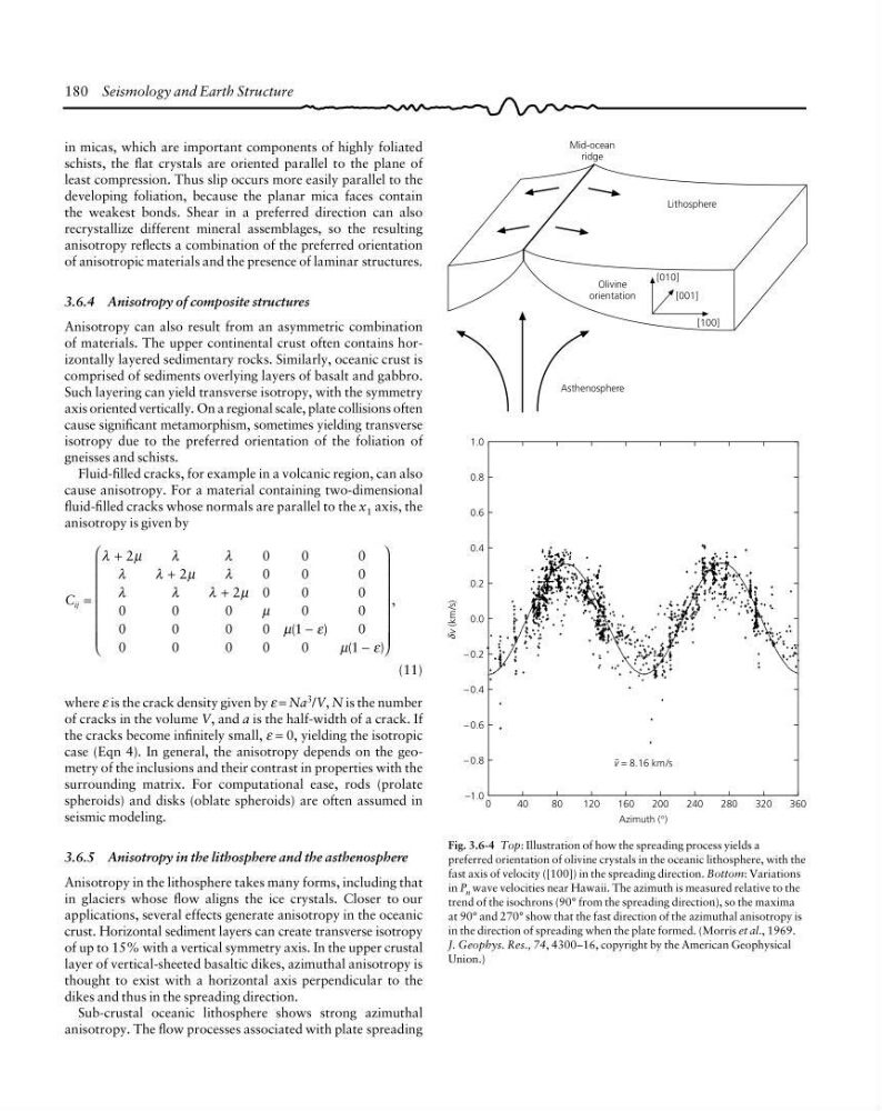
anisotropy. The flow processes associated with plate spreading
Fig. 3.6-4 Top: Illustration of how the spreading process yields a
preferred orientation of olivine crystals in the oceanic lithosphere, with the
fast axis of velocity ([100]) in the spreading direction. Bottom: Variations
in P n wave velocities near Hawaii. The azimuth is measured relative to the
trend of the isochrons (90° from the spreading direction), so the maxima
at 90° and 270° show that the fast direction of the azimuthal anisotropy is
in the direction of spreading when the plate formed. (Morris et al., 1969.
J. Geophys. Res., 74, 4300–16, copyright by the American Geophysical
Union.)
v (km/s)
360
Mid-ocean
ridge
Olivine
orientation
Lithosphere
[010]
[001]
[100]
Asthenosphere
v = 8.16 km/s
Azimuth (°)
0
1.0
0.8
0.6
0.4
0.2
0.0
– 0.2
– 0.4
– 0.6
– 0.8
–1.0
40
80
120
160
200
240
280
320
δ
in micas, which are important components of highly foliated
schists, the flat crystals are oriented parallel to the plane of
least compression. Thus slip occurs more easily parallel to the
developing foliation, because the planar mica faces contain
the weakest bonds. Shear in a preferred direction can also
recrystallize different mineral assemblages, so the resulting
anisotropy reflects a combination of the preferred orientation
of anisotropic materials and the presence of laminar structures.
3.6.4 Anisotropy of composite structures
Anisotropy can also result from an asymmetric combination
of materials. The upper continental crust often contains horizontally layered sedimentary rocks. Similarly, oceanic crust is
comprised of sediments overlying layers of basalt and gabbro.
Such layering can yield transverse isotropy, with the symmetry
axis oriented vertically. On a regional scale, plate collisions often
cause significant metamorphism, sometimes yielding transverse
isotropy due to the preferred orientation of the foliation of
gneisses and schists.
Fluid-filled cracks, for example in a volcanic region, can also
cause anisotropy. For a material containing two-dimensional
fluid-filled cracks whose normals are parallel to the x 1 axis, the
anisotropy is given by
C ij =
+
+
+
−
−
⎛
⎝
⎜
⎜
⎜
⎜
⎜
⎜ ⎜
⎞
⎠
⎟
⎟
⎟
⎟
⎟
⎟ ⎟
(
)
(
)
,
λ
µ
λ
λ
λ
λ
µ
λ
λ
λ
λ
µ
µ
µ
ε
µ
ε
2
0
0
0
2
0
0
0
2
0
0
0
0
0
0
0
0
0
0
0
0
1
0
0
0
0
0
0
1
(11)
where ε is the crack density given by ε = Na 3 /V, N is the number
of cracks in the volume V, and a is the half-width of a crack. If
the cracks become infinitely small, ε = 0, yielding the isotropic
case (Eqn 4). In general, the anisotropy depends on the geometry of the inclusions and their contrast in properties with the
surrounding matrix. For computational ease, rods (prolate
spheroids) and disks (oblate spheroids) are often assumed in
seismic modeling.
3.6.5 Anisotropy in the lithosphere and the asthenosphere
Anisotropy in the lithosphere takes many forms, including that
in glaciers whose flow aligns the ice crystals. Closer to our
applications, several effects generate anisotropy in the oceanic
crust. Horizontal sediment layers can create transverse isotropy
of up to 15% with a vertical symmetry axis. In the upper crustal
layer of vertical-sheeted basaltic dikes, azimuthal anisotropy is
thought to exist with a horizontal axis perpendicular to the
dikes and thus in the spreading direction.
Sub-crustal oceanic lithosphere shows strong azimuthal
anisotropy. The flow processes associated with plate spreading
Fig. 3.6-4 Top: Illustration of how the spreading process yields a
preferred orientation of olivine crystals in the oceanic lithosphere, with the
fast axis of velocity ([100]) in the spreading direction. Bottom: Variations
in P n wave velocities near Hawaii. The azimuth is measured relative to the
trend of the isochrons (90° from the spreading direction), so the maxima
at 90° and 270° show that the fast direction of the azimuthal anisotropy is
in the direction of spreading when the plate formed. (Morris et al., 1969.
J. Geophys. Res., 74, 4300–16, copyright by the American Geophysical
Union.)
v (km/s)
360
Mid-ocean
ridge
Olivine
orientation
Lithosphere
[010]
[001]
[100]
Asthenosphere
v = 8.16 km/s
Azimuth (°)
0
1.0
0.8
0.6
0.4
0.2
0.0
– 0.2
– 0.4
– 0.6
– 0.8
–1.0
40
80
120
160
200
240
280
320
δ