

158 Seismology and Earth Structure
Ray
parameter
p
p + dp
d∆
v 0 dT
r 0 d∆
i
i
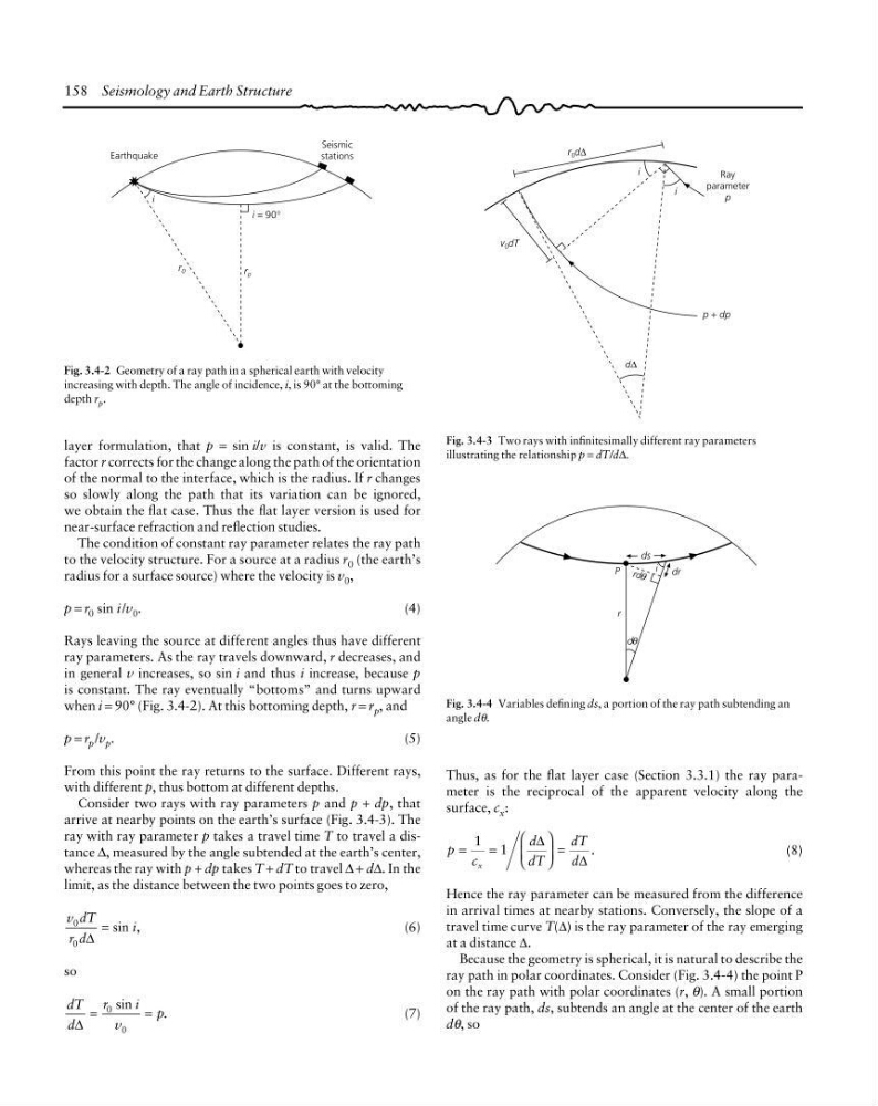
Fig. 3.4-2 Geometry of a ray path in a spherical earth with velocity
increasing with depth. The angle of incidence, i, is 90° at the bottoming
depth r p .
Fig. 3.4-3 Two rays with infinitesimally different ray parameters
illustrating the relationship p = dT/d∆.
Seismic
stations
Earthquake
i = 90°
r p
r 0
i
layer formulation, that p = sin i/v is constant, is valid. The
factor r corrects for the change along the path of the orientation
of the normal to the interface, which is the radius. If r changes
so slowly along the path that its variation can be ignored,
we obtain the flat case. Thus the flat layer version is used for
near-surface refraction and reflection studies.
The condition of constant ray parameter relates the ray path
to the velocity structure. For a source at a radius r 0 (the earth’s
radius for a surface source) where the velocity is v 0 ,
p = r 0 sin i /v 0 .
(4)
Rays leaving the source at different angles thus have different
ray parameters. As the ray travels downward, r decreases, and
in general v increases, so sin i and thus i increase, because p
is constant. The ray eventually “bottoms” and turns upward
when i = 90° (Fig. 3.4-2). At this bottoming depth, r = r p , and
p = r p /v p .
(5)
From this point the ray returns to the surface. Different rays,
with different p, thus bottom at different depths.
Consider two rays with ray parameters p and p + dp, that
arrive at nearby points on the earth’s surface (Fig. 3.4-3). The
ray with ray parameter p takes a travel time T to travel a distance ∆, measured by the angle subtended at the earth’s center,
whereas the ray with p + dp takes T + dT to travel ∆ + d∆. In the
limit, as the distance between the two points goes to zero,
v dT
r d
i
0
0 ∆
sin ,
=
(6)
so
dT
d
r
i
v
p
∆
sin
.
=
=
0
0
(7)
Fig. 3.4-4 Variables defining ds, a portion of the ray path subtending an
angle dθ.
d
i
rd θ
θ
r
P
ds
dr
Thus, as for the flat layer case (Section 3.3.1) the ray parameter is the reciprocal of the apparent velocity along the
surface, c x :
p
c
d
dT
dT
d
x
.
=
=
⎛
⎝
⎜
⎞
⎠
⎟ =
1 1
∆
∆
(8)
Hence the ray parameter can be measured from the difference
in arrival times at nearby stations. Conversely, the slope of a
travel time curve T(∆) is the ray parameter of the ray emerging
at a distance ∆.
Because the geometry is spherical, it is natural to describe the
ray path in polar coordinates. Consider (Fig. 3.4-4) the point P
on the ray path with polar coordinates (r, θ). A small portion
of the ray path, ds, subtends an angle at the center of the earth
dθ, so
Ray
parameter
p
p + dp
d∆
v 0 dT
r 0 d∆
i
i
Fig. 3.4-2 Geometry of a ray path in a spherical earth with velocity
increasing with depth. The angle of incidence, i, is 90° at the bottoming
depth r p .
Fig. 3.4-3 Two rays with infinitesimally different ray parameters
illustrating the relationship p = dT/d∆.
Seismic
stations
Earthquake
i = 90°
r p
r 0
i
layer formulation, that p = sin i/v is constant, is valid. The
factor r corrects for the change along the path of the orientation
of the normal to the interface, which is the radius. If r changes
so slowly along the path that its variation can be ignored,
we obtain the flat case. Thus the flat layer version is used for
near-surface refraction and reflection studies.
The condition of constant ray parameter relates the ray path
to the velocity structure. For a source at a radius r 0 (the earth’s
radius for a surface source) where the velocity is v 0 ,
p = r 0 sin i /v 0 .
(4)
Rays leaving the source at different angles thus have different
ray parameters. As the ray travels downward, r decreases, and
in general v increases, so sin i and thus i increase, because p
is constant. The ray eventually “bottoms” and turns upward
when i = 90° (Fig. 3.4-2). At this bottoming depth, r = r p , and
p = r p /v p .
(5)
From this point the ray returns to the surface. Different rays,
with different p, thus bottom at different depths.
Consider two rays with ray parameters p and p + dp, that
arrive at nearby points on the earth’s surface (Fig. 3.4-3). The
ray with ray parameter p takes a travel time T to travel a distance ∆, measured by the angle subtended at the earth’s center,
whereas the ray with p + dp takes T + dT to travel ∆ + d∆. In the
limit, as the distance between the two points goes to zero,
v dT
r d
i
0
0 ∆
sin ,
=
(6)
so
dT
d
r
i
v
p
∆
sin
.
=
=
0
0
(7)
Fig. 3.4-4 Variables defining ds, a portion of the ray path subtending an
angle dθ.
d
i
rd θ
θ
r
P
ds
dr
Thus, as for the flat layer case (Section 3.3.1) the ray parameter is the reciprocal of the apparent velocity along the
surface, c x :
p
c
d
dT
dT
d
x
.
=
=
⎛
⎝
⎜
⎞
⎠
⎟ =
1 1
∆
∆
(8)
Hence the ray parameter can be measured from the difference
in arrival times at nearby stations. Conversely, the slope of a
travel time curve T(∆) is the ray parameter of the ray emerging
at a distance ∆.
Because the geometry is spherical, it is natural to describe the
ray path in polar coordinates. Consider (Fig. 3.4-4) the point P
on the ray path with polar coordinates (r, θ). A small portion
of the ray path, ds, subtends an angle at the center of the earth
dθ, so