

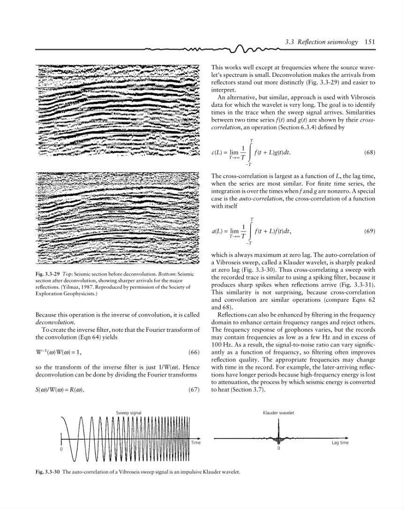
This works well except at frequencies where the source wavelet’s spectrum is small. Deconvolution makes the arrivals from
reflectors stand out more distinctly (Fig. 3.3-29) and easier to
interpret.
An alternative, but similar, approach is used with Vibroseis
data for which the wavelet is very long. The goal is to identify
times in the trace when the sweep signal arrives. Similarities
between two time series f(t) and g(t) are shown by their crosscorrelation, an operation (Section 6.3.4) defined by
c L
T
f t L g t dt
T
T
T
( ) lim
(
) ( ) .
=
+
→∞
−
1
Ύ
(68)
The cross-correlation is largest as a function of L, the lag time,
when the series are most similar. For finite time series, the
integration is over the times when f and g are nonzero. A special
case is the auto-correlation, the cross-correlation of a function
with itself
a L
T
f t L f t dt
T
T
T
( ) lim
(
) ( ) ,
=
+
→∞
−
1
Ύ
(69)
which is always maximum at zero lag. The auto-correlation of
a Vibroseis sweep, called a Klauder wavelet, is sharply peaked
at zero lag (Fig. 3.3-30). Thus cross-correlating a sweep with
the recorded trace is similar to using a spiking filter, because it
produces sharp spikes when reflections arrive (Fig. 3.3-31).
This similarity is not surprising, because cross-correlation
and convolution are similar operations (compare Eqns 62
and 68).
Reflections can also be enhanced by filtering in the frequency
domain to enhance certain frequency ranges and reject others.
The frequency response of geophones varies, but the records
may contain frequencies as low as a few Hz and in excess of
100 Hz. As a result, the signal-to-noise ratio can vary significantly as a function of frequency, so filtering often improves
reflection quality. The appropriate frequencies may change
with time in the record. For example, the later-arriving reflections have longer periods because high-frequency energy is lost
to attenuation, the process by which seismic energy is converted
to heat (Section 3.7).
3.3 Reflection seismology 151
Fig. 3.3-29 Top: Seismic section before deconvolution. Bottom: Seismic
section after deconvolution, showing sharper arrivals for the major
reflections. (Yilmaz, 1987. Reproduced by permission of the Society of
Exploration Geophysicists.)
Fig. 3.3-30 The auto-correlation of a Vibroseis sweep signal is an impulsive Klauder wavelet.
0
Time
Sweep signal
Klauder wavelet
Lag time
0
Because this operation is the inverse of convolution, it is called
deconvolution.
To create the inverse filter, note that the Fourier transform of
the convolution (Eqn 64) yields
W
−1
(ω)W(ω) = 1,
(66)
so the transform of the inverse filter is just 1/W(ω). Hence
deconvolution can be done by dividing the Fourier transforms
S(ω)/W(ω) = R(ω).
(67)
reflectors stand out more distinctly (Fig. 3.3-29) and easier to
interpret.
An alternative, but similar, approach is used with Vibroseis
data for which the wavelet is very long. The goal is to identify
times in the trace when the sweep signal arrives. Similarities
between two time series f(t) and g(t) are shown by their crosscorrelation, an operation (Section 6.3.4) defined by
c L
T
f t L g t dt
T
T
T
( ) lim
(
) ( ) .
=
+
→∞
−
1
Ύ
(68)
The cross-correlation is largest as a function of L, the lag time,
when the series are most similar. For finite time series, the
integration is over the times when f and g are nonzero. A special
case is the auto-correlation, the cross-correlation of a function
with itself
a L
T
f t L f t dt
T
T
T
( ) lim
(
) ( ) ,
=
+
→∞
−
1
Ύ
(69)
which is always maximum at zero lag. The auto-correlation of
a Vibroseis sweep, called a Klauder wavelet, is sharply peaked
at zero lag (Fig. 3.3-30). Thus cross-correlating a sweep with
the recorded trace is similar to using a spiking filter, because it
produces sharp spikes when reflections arrive (Fig. 3.3-31).
This similarity is not surprising, because cross-correlation
and convolution are similar operations (compare Eqns 62
and 68).
Reflections can also be enhanced by filtering in the frequency
domain to enhance certain frequency ranges and reject others.
The frequency response of geophones varies, but the records
may contain frequencies as low as a few Hz and in excess of
100 Hz. As a result, the signal-to-noise ratio can vary significantly as a function of frequency, so filtering often improves
reflection quality. The appropriate frequencies may change
with time in the record. For example, the later-arriving reflections have longer periods because high-frequency energy is lost
to attenuation, the process by which seismic energy is converted
to heat (Section 3.7).
3.3 Reflection seismology 151
Fig. 3.3-29 Top: Seismic section before deconvolution. Bottom: Seismic
section after deconvolution, showing sharper arrivals for the major
reflections. (Yilmaz, 1987. Reproduced by permission of the Society of
Exploration Geophysicists.)
Fig. 3.3-30 The auto-correlation of a Vibroseis sweep signal is an impulsive Klauder wavelet.
0
Time
Sweep signal
Klauder wavelet
Lag time
0
Because this operation is the inverse of convolution, it is called
deconvolution.
To create the inverse filter, note that the Fourier transform of
the convolution (Eqn 64) yields
W
−1
(ω)W(ω) = 1,
(66)
so the transform of the inverse filter is just 1/W(ω). Hence
deconvolution can be done by dividing the Fourier transforms
S(ω)/W(ω) = R(ω).
(67)