

148 Seismology and Earth Structure
Field record
0
1
2
3
τ (s)
100
Time (s)
0
1
2
3
200
300
400
500
600
700 800
900
1.5
1.2
3
p
(10
−6 s/m)
C x
(km/s)
τ −p Transform
Time (s)
0
1
2
3
After −p
τ
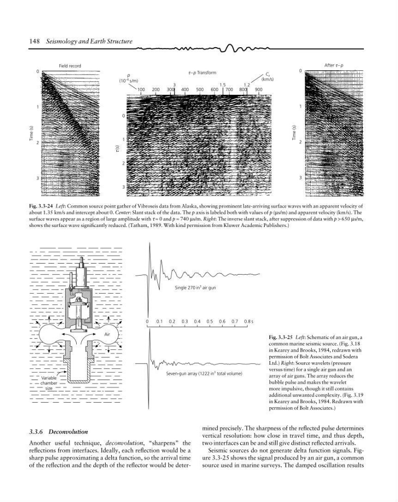
Fig. 3.3-24 Left: Common source point gather of Vibroseis data from Alaska, showing prominent late-arriving surface waves with an apparent velocity of
about 1.35 km/s and intercept about 0. Center: Slant stack of the data. The p axis is labeled both with values of p (µs/m) and apparent velocity (km/s). The
surface waves appear as a region of large amplitude with τ ≈ 0 and p ≈ 740 µs/m. Right: The inverse slant stack, after suppression of data with p > 650 µs/m,
shows the surface wave significantly reduced. (Tatham, 1989. With kind permission from Kluwer Academic Publishers.)
Variable
chamber
size
Air
0
Seven-gun array (1222 in
3 total volume)
Single 270 in
3 air gun
0.1 0.2 0.3 0.4 0.5 0.6 0.7 0.8 s
Fig. 3.3-25 Left: Schematic of an air gun, a
common marine seismic source. (Fig. 3.18
in Kearey and Brooks, 1984, redrawn with
permission of Bolt Associates and Sodera
Ltd.) Right: Source wavelets (pressure
versus time) for a single air gun and an
array of air guns. The array reduces the
bubble pulse and makes the wavelet
more impulsive, though it still contains
additional unwanted complexity. (Fig. 3.19
in Kearey and Brooks, 1984. Redrawn with
permission of Bolt Associates.)
mined precisely. The sharpness of the reflected pulse determines
vertical resolution: how close in travel time, and thus depth,
two interfaces can be and still give distinct reflected arrivals.
Seismic sources do not generate delta function signals. Figure 3.3-25 shows the signal produced by an air gun, a common
source used in marine surveys. The damped oscillation results
3.3.6 Deconvolution
Another useful technique, deconvolution, “sharpens” the
reflections from interfaces. Ideally, each reflection would be a
sharp pulse approximating a delta function, so the arrival time
of the reflection and the depth of the reflector would be deter-
Field record
0
1
2
3
τ (s)
100
Time (s)
0
1
2
3
200
300
400
500
600
700 800
900
1.5
1.2
3
p
(10
−6 s/m)
C x
(km/s)
τ −p Transform
Time (s)
0
1
2
3
After −p
τ
Fig. 3.3-24 Left: Common source point gather of Vibroseis data from Alaska, showing prominent late-arriving surface waves with an apparent velocity of
about 1.35 km/s and intercept about 0. Center: Slant stack of the data. The p axis is labeled both with values of p (µs/m) and apparent velocity (km/s). The
surface waves appear as a region of large amplitude with τ ≈ 0 and p ≈ 740 µs/m. Right: The inverse slant stack, after suppression of data with p > 650 µs/m,
shows the surface wave significantly reduced. (Tatham, 1989. With kind permission from Kluwer Academic Publishers.)
Variable
chamber
size
Air
0
Seven-gun array (1222 in
3 total volume)
Single 270 in
3 air gun
0.1 0.2 0.3 0.4 0.5 0.6 0.7 0.8 s
Fig. 3.3-25 Left: Schematic of an air gun, a
common marine seismic source. (Fig. 3.18
in Kearey and Brooks, 1984, redrawn with
permission of Bolt Associates and Sodera
Ltd.) Right: Source wavelets (pressure
versus time) for a single air gun and an
array of air guns. The array reduces the
bubble pulse and makes the wavelet
more impulsive, though it still contains
additional unwanted complexity. (Fig. 3.19
in Kearey and Brooks, 1984. Redrawn with
permission of Bolt Associates.)
mined precisely. The sharpness of the reflected pulse determines
vertical resolution: how close in travel time, and thus depth,
two interfaces can be and still give distinct reflected arrivals.
Seismic sources do not generate delta function signals. Figure 3.3-25 shows the signal produced by an air gun, a common
source used in marine surveys. The damped oscillation results
3.3.6 Deconvolution
Another useful technique, deconvolution, “sharpens” the
reflections from interfaces. Ideally, each reflection would be a
sharp pulse approximating a delta function, so the arrival time
of the reflection and the depth of the reflector would be deter-