

144 Seismology and Earth Structure
Fig. 3.3-19 Top: Traces with a common midpoint sample the same point
on a reflector when a reflector and the structure above it are horizontal.
Bottom: If the structure dips, traces with a common midpoint do not
reflect at the same point. (After Kearey and Brooks, 1984.)
to produce a zero-offset trace for that midpoint. These traces
together form a zero-offset seismic section, u(m, 0, t), a function of midpoint and time. This section simulates moving along
the survey line with a single source and receiver at the same
location, and recording arrivals from below as a function of
time. Because this process reduces the volume of data dramatically, there is a tendency to conduct processing operations after,
rather than before, stacking when possible.
Often a CMP stack is referred to as a CDP, or common depth
point, stack. CMP is a better term, because traces with the same
midpoint have the same reflection point at depth only when a
reflector and the structure above it are flat-lying (Fig. 3.3-19).
This effect is generally small enough that CMP stacking is
useful. We will discuss shortly the limitations on reflection
studies due to deviations from the ideal flat geometry.
A seismic section is in some ways similar to a “picture” of the
subsurface. Major arrivals in the data generally represent significant reflectors at depth, and can be correlated with geologic
structure. As a result, analysis of seismic reflection data is a
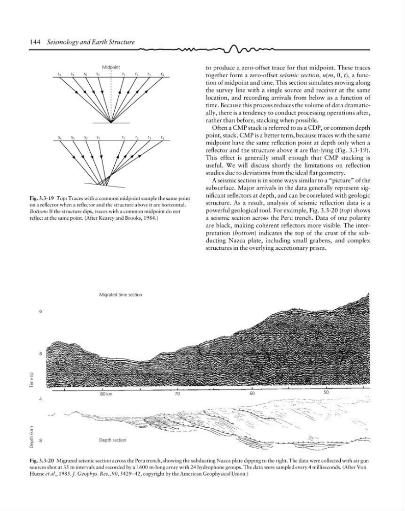
powerful geological tool. For example, Fig. 3.3-20 (top) shows
a seismic section across the Peru trench. Data of one polarity
are black, making coherent reflectors more visible. The interpretation (bottom) indicates the top of the crust of the subducting Nazca plate, including small grabens, and complex
structures in the overlying accretionary prism.
Midpoint
s 4
s 3
s 2
s 1
r 1
r 2
r 3
r 4
s 4
s 3
s 2
s 1
r 1
r 2
r 3
r 4
Depth (km)
Time (s)
4
8
Depth section
Migrated time section
6
8
80 km
70
60
50
Fig. 3.3-20 Migrated seismic section across the Peru trench, showing the subducting Nazca plate dipping to the right. The data were collected with air gun
sources shot at 35 m intervals and recorded by a 1600 m-long array with 24 hydrophone groups. The data were sampled every 4 milliseconds. (After Von
Huene et al., 1985. J. Geophys. Res., 90, 5429–42, copyright by the American Geophysical Union.)
Fig. 3.3-19 Top: Traces with a common midpoint sample the same point
on a reflector when a reflector and the structure above it are horizontal.
Bottom: If the structure dips, traces with a common midpoint do not
reflect at the same point. (After Kearey and Brooks, 1984.)
to produce a zero-offset trace for that midpoint. These traces
together form a zero-offset seismic section, u(m, 0, t), a function of midpoint and time. This section simulates moving along
the survey line with a single source and receiver at the same
location, and recording arrivals from below as a function of
time. Because this process reduces the volume of data dramatically, there is a tendency to conduct processing operations after,
rather than before, stacking when possible.
Often a CMP stack is referred to as a CDP, or common depth
point, stack. CMP is a better term, because traces with the same
midpoint have the same reflection point at depth only when a
reflector and the structure above it are flat-lying (Fig. 3.3-19).
This effect is generally small enough that CMP stacking is
useful. We will discuss shortly the limitations on reflection
studies due to deviations from the ideal flat geometry.
A seismic section is in some ways similar to a “picture” of the
subsurface. Major arrivals in the data generally represent significant reflectors at depth, and can be correlated with geologic
structure. As a result, analysis of seismic reflection data is a
powerful geological tool. For example, Fig. 3.3-20 (top) shows
a seismic section across the Peru trench. Data of one polarity
are black, making coherent reflectors more visible. The interpretation (bottom) indicates the top of the crust of the subducting Nazca plate, including small grabens, and complex
structures in the overlying accretionary prism.
Midpoint
s 4
s 3
s 2
s 1
r 1
r 2
r 3
r 4
s 4
s 3
s 2
s 1
r 1
r 2
r 3
r 4
Depth (km)
Time (s)
4
8
Depth section
Migrated time section
6
8
80 km
70
60
50
Fig. 3.3-20 Migrated seismic section across the Peru trench, showing the subducting Nazca plate dipping to the right. The data were collected with air gun
sources shot at 35 m intervals and recorded by a 1600 m-long array with 24 hydrophone groups. The data were sampled every 4 milliseconds. (After Von
Huene et al., 1985. J. Geophys. Res., 90, 5429–42, copyright by the American Geophysical Union.)