

142 Seismology and Earth Structure
Direct
wave
Head
wave
Reflected
wave
Seismograms
Offset, x
t 0
Time, t
Time, t
t 0
Normal moveout
Offset, x
Fig. 3.3-14 Geometry of various multiple reflections. (After Kearey and
Brooks, 1984.)
Primary
Double-path
multiple
Near-surface
multiple
Peg-leg
multiple
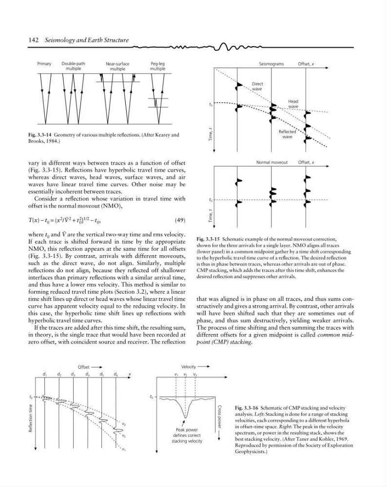
Fig. 3.3-15 Schematic example of the normal moveout correction,
shown for the three arrivals for a single layer. NMO aligns all traces
(lower panel) in a common midpoint gather by a time shift corresponding
to the hyperbolic travel time curve of a reflection. The desired reflection
is thus in phase between traces, whereas other arrivals are out of phase.
CMP stacking, which adds the traces after this time shift, enhances the
desired reflection and suppresses other arrivals.
that was aligned is in phase on all traces, and thus sums constructively and gives a strong arrival. By contrast, other arrivals
will have been shifted such that they are sometimes out of
phase, and thus sum destructively, yielding weaker arrivals.
The process of time shifting and then summing the traces with
different offsets for a given midpoint is called common midpoint (CMP) stacking.
Reflection time
Offset
v 3
v 2
v 1
t 0
d 1
d 2
d 3
d 4
d 5
d 6
x
Peak power
defines correct
stacking velocity
Cross power
t 0
v 2 v 3
v 1
Velocity
Fig. 3.3-16 Schematic of CMP stacking and velocity
analysis. Left: Stacking is done for a range of stacking
velocities, each corresponding to a different hyperbola
in offset–time space. Right: The peak in the velocity
spectrum, or power in the resulting stack, shows the
best stacking velocity. (After Taner and Kohler, 1969.
Reproduced by permission of the Society of Exploration
Geophysicists.)
vary in different ways between traces as a function of offset
(Fig. 3.3-15). Reflections have hyperbolic travel time curves,
whereas direct waves, head waves, surface waves, and air
waves have linear travel time curves. Other noise may be
essentially incoherent between traces.
Consider a reflection whose variation in travel time with
offset is the normal moveout (NMO),
T(x) − t 0 = (x 2 /E 2 + t 2
0 ] 1/2 − t 0 ,
(49)
where t 0 and E are the vertical two-way time and rms velocity.
If each trace is shifted forward in time by the appropriate
NMO, this reflection appears at the same time for all offsets
(Fig. 3.3-15). By contrast, arrivals with different moveouts,
such as the direct wave, do not align. Similarly, multiple
reflections do not align, because they reflected off shallower
interfaces than primary reflections with a similar arrival time,
and thus have a lower rms velocity. This method is similar to
forming reduced travel time plots (Section 3.2), where a linear
time shift lines up direct or head waves whose linear travel time
curve has apparent velocity equal to the reducing velocity. In
this case, the hyperbolic time shift lines up reflections with
hyperbolic travel time curves.
If the traces are added after this time shift, the resulting sum,
in theory, is the single trace that would have been recorded at
zero offset, with coincident source and receiver. The reflection
Direct
wave
Head
wave
Reflected
wave
Seismograms
Offset, x
t 0
Time, t
Time, t
t 0
Normal moveout
Offset, x
Fig. 3.3-14 Geometry of various multiple reflections. (After Kearey and
Brooks, 1984.)
Primary
Double-path
multiple
Near-surface
multiple
Peg-leg
multiple
Fig. 3.3-15 Schematic example of the normal moveout correction,
shown for the three arrivals for a single layer. NMO aligns all traces
(lower panel) in a common midpoint gather by a time shift corresponding
to the hyperbolic travel time curve of a reflection. The desired reflection
is thus in phase between traces, whereas other arrivals are out of phase.
CMP stacking, which adds the traces after this time shift, enhances the
desired reflection and suppresses other arrivals.
that was aligned is in phase on all traces, and thus sums constructively and gives a strong arrival. By contrast, other arrivals
will have been shifted such that they are sometimes out of
phase, and thus sum destructively, yielding weaker arrivals.
The process of time shifting and then summing the traces with
different offsets for a given midpoint is called common midpoint (CMP) stacking.
Reflection time
Offset
v 3
v 2
v 1
t 0
d 1
d 2
d 3
d 4
d 5
d 6
x
Peak power
defines correct
stacking velocity
Cross power
t 0
v 2 v 3
v 1
Velocity
Fig. 3.3-16 Schematic of CMP stacking and velocity
analysis. Left: Stacking is done for a range of stacking
velocities, each corresponding to a different hyperbola
in offset–time space. Right: The peak in the velocity
spectrum, or power in the resulting stack, shows the
best stacking velocity. (After Taner and Kohler, 1969.
Reproduced by permission of the Society of Exploration
Geophysicists.)
vary in different ways between traces as a function of offset
(Fig. 3.3-15). Reflections have hyperbolic travel time curves,
whereas direct waves, head waves, surface waves, and air
waves have linear travel time curves. Other noise may be
essentially incoherent between traces.
Consider a reflection whose variation in travel time with
offset is the normal moveout (NMO),
T(x) − t 0 = (x 2 /E 2 + t 2
0 ] 1/2 − t 0 ,
(49)
where t 0 and E are the vertical two-way time and rms velocity.
If each trace is shifted forward in time by the appropriate
NMO, this reflection appears at the same time for all offsets
(Fig. 3.3-15). By contrast, arrivals with different moveouts,
such as the direct wave, do not align. Similarly, multiple
reflections do not align, because they reflected off shallower
interfaces than primary reflections with a similar arrival time,
and thus have a lower rms velocity. This method is similar to
forming reduced travel time plots (Section 3.2), where a linear
time shift lines up direct or head waves whose linear travel time
curve has apparent velocity equal to the reducing velocity. In
this case, the hyperbolic time shift lines up reflections with
hyperbolic travel time curves.
If the traces are added after this time shift, the resulting sum,
in theory, is the single trace that would have been recorded at
zero offset, with coincident source and receiver. The reflection