

3.3 Reflection seismology 141
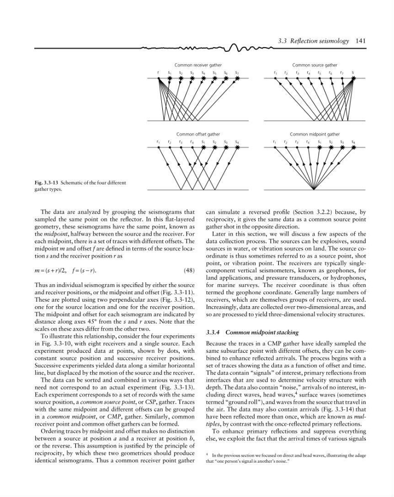
Fig. 3.3-13 Schematic of the four different
gather types.
r
s 1
s 2
s 3
s 4
s 5
s 6
s 7
Common receiver gather
r 1
r 2
r 3
r 4
r 5
r 6
r 7
s
Common source gather
r 2
r 3
r 4
s 1
s 2
s 3
s 4
Common offset gather
r 2
r 3
r 4
s 1
s 2
s 3
s 4
Common midpoint gather
r 1
r 1
4 In the previous section we focused on direct and head waves, illustrating the adage
that “one person’s signal is another’s noise.”
can simulate a reversed profile (Section 3.2.2) because, by
reciprocity, it gives the same data as a common source point
gather shot in the opposite direction.
Later in this section, we will discuss a few aspects of the
data collection process. The sources can be explosives, sound
sources in water, or vibration sources on land. The source coordinate is thus sometimes referred to as a source point, shot
point, or vibration point. The receivers are typically singlecomponent vertical seismometers, known as geophones, for
land applications, and pressure transducers, or hydrophones,
for marine surveys. The receiver coordinate is thus often
termed the geophone coordinate. Generally large numbers of
receivers, which are themselves groups of receivers, are used.
Increasingly, data are collected over two-dimensional areas, and
so are processed to yield three-dimensional velocity structures.
3.3.4 Common midpoint stacking
Because the traces in a CMP gather have ideally sampled the
same subsurface point with different offsets, they can be combined to enhance reflected arrivals. The process begins with a
set of traces showing the data as a function of offset and time.
The data contain “signals” of interest, primary reflections from
interfaces that are used to determine velocity structure with
depth. The data also contain “noise,” arrivals of no interest, including direct waves, head waves, 4 surface waves (sometimes
termed “ground roll”), and waves from the source that travel in
the air. The data may also contain arrivals (Fig. 3.3-14) that
have been reflected more than once, which are known as multiples, by contrast with the once-reflected primary reflections.
To enhance primary reflections and suppress everything
else, we exploit the fact that the arrival times of various signals
The data are analyzed by grouping the seismograms that
sampled the same point on the reflector. In this flat-layered
geometry, these seismograms have the same point, known as
the midpoint, halfway between the source and the receiver. For
each midpoint, there is a set of traces with different offsets. The
midpoint m and offset f are defined in terms of the source location s and the receiver position r as
m = (s + r)/2, f = (s − r).
(48)
Thus an individual seismogram is specified by either the source
and receiver positions, or the midpoint and offset (Fig. 3.3-11).
These are plotted using two perpendicular axes (Fig. 3.3-12),
one for the source location and one for the receiver position.
The midpoint and offset for each seismogram are indicated by
distance along axes 45° from the s and r axes. Note that the
scales on these axes differ from the other two.
To illustrate this relationship, consider the four experiments
in Fig. 3.3-10, with eight receivers and a single source. Each
experiment produced data at points, shown by dots, with
constant source position and successive receiver positions.
Successive experiments yielded data along a similar horizontal
line, but displaced by the motion of the source and the receiver.
The data can be sorted and combined in various ways that
need not correspond to an actual experiment (Fig. 3.3-13).
Each experiment corresponds to a set of records with the same
source position, a common source point, or CSP, gather. Traces
with the same midpoint and different offsets can be grouped
in a common midpoint, or CMP, gather. Similarly, common
receiver point and common offset gathers can be formed.
Ordering traces by midpoint and offset makes no distinction
between a source at position a and a receiver at position b,
or the reverse. This assumption is justified by the principle of
reciprocity, by which these two geometrices should produce
identical seismograms. Thus a common receiver point gather
Fig. 3.3-13 Schematic of the four different
gather types.
r
s 1
s 2
s 3
s 4
s 5
s 6
s 7
Common receiver gather
r 1
r 2
r 3
r 4
r 5
r 6
r 7
s
Common source gather
r 2
r 3
r 4
s 1
s 2
s 3
s 4
Common offset gather
r 2
r 3
r 4
s 1
s 2
s 3
s 4
Common midpoint gather
r 1
r 1
4 In the previous section we focused on direct and head waves, illustrating the adage
that “one person’s signal is another’s noise.”
can simulate a reversed profile (Section 3.2.2) because, by
reciprocity, it gives the same data as a common source point
gather shot in the opposite direction.
Later in this section, we will discuss a few aspects of the
data collection process. The sources can be explosives, sound
sources in water, or vibration sources on land. The source coordinate is thus sometimes referred to as a source point, shot
point, or vibration point. The receivers are typically singlecomponent vertical seismometers, known as geophones, for
land applications, and pressure transducers, or hydrophones,
for marine surveys. The receiver coordinate is thus often
termed the geophone coordinate. Generally large numbers of
receivers, which are themselves groups of receivers, are used.
Increasingly, data are collected over two-dimensional areas, and
so are processed to yield three-dimensional velocity structures.
3.3.4 Common midpoint stacking
Because the traces in a CMP gather have ideally sampled the
same subsurface point with different offsets, they can be combined to enhance reflected arrivals. The process begins with a
set of traces showing the data as a function of offset and time.
The data contain “signals” of interest, primary reflections from
interfaces that are used to determine velocity structure with
depth. The data also contain “noise,” arrivals of no interest, including direct waves, head waves, 4 surface waves (sometimes
termed “ground roll”), and waves from the source that travel in
the air. The data may also contain arrivals (Fig. 3.3-14) that
have been reflected more than once, which are known as multiples, by contrast with the once-reflected primary reflections.
To enhance primary reflections and suppress everything
else, we exploit the fact that the arrival times of various signals
The data are analyzed by grouping the seismograms that
sampled the same point on the reflector. In this flat-layered
geometry, these seismograms have the same point, known as
the midpoint, halfway between the source and the receiver. For
each midpoint, there is a set of traces with different offsets. The
midpoint m and offset f are defined in terms of the source location s and the receiver position r as
m = (s + r)/2, f = (s − r).
(48)
Thus an individual seismogram is specified by either the source
and receiver positions, or the midpoint and offset (Fig. 3.3-11).
These are plotted using two perpendicular axes (Fig. 3.3-12),
one for the source location and one for the receiver position.
The midpoint and offset for each seismogram are indicated by
distance along axes 45° from the s and r axes. Note that the
scales on these axes differ from the other two.
To illustrate this relationship, consider the four experiments
in Fig. 3.3-10, with eight receivers and a single source. Each
experiment produced data at points, shown by dots, with
constant source position and successive receiver positions.
Successive experiments yielded data along a similar horizontal
line, but displaced by the motion of the source and the receiver.
The data can be sorted and combined in various ways that
need not correspond to an actual experiment (Fig. 3.3-13).
Each experiment corresponds to a set of records with the same
source position, a common source point, or CSP, gather. Traces
with the same midpoint and different offsets can be grouped
in a common midpoint, or CMP, gather. Similarly, common
receiver point and common offset gathers can be formed.
Ordering traces by midpoint and offset makes no distinction
between a source at position a and a receiver at position b,
or the reverse. This assumption is justified by the principle of
reciprocity, by which these two geometrices should produce
identical seismograms. Thus a common receiver point gather