

140 Seismology and Earth Structure
CSP
gather
10
20
Offset
f = s − r
10
5
1 5
2 0
Receiver
r
0
5
10
15
20
10
5
15
20
Midpoint
m = (s + r)/2
Source
s
CMP gather
Horizontal
interface
Depth
m
s
r
x = 0
x
r
f
s
m
Offset = 2
x = 0
5
1 0
r = 7
s = 9
Offset = 4
r = 6
s = 10
Offset = 6
r = 5
s = 11
Offset = 8
r = 4
s = 12
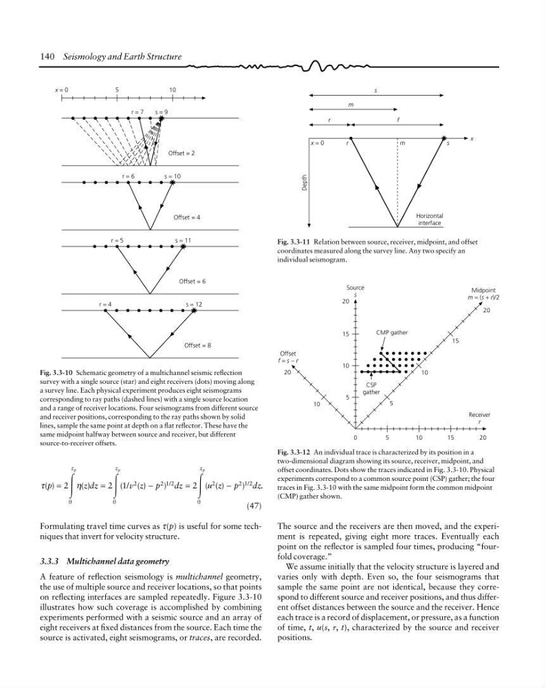
Fig. 3.3-10 Schematic geometry of a multichannel seismic reflection
survey with a single source (star) and eight receivers (dots) moving along
a survey line. Each physical experiment produces eight seismograms
corresponding to ray paths (dashed lines) with a single source location
and a range of receiver locations. Four seismograms from different source
and receiver positions, corresponding to the ray paths shown by solid
lines, sample the same point at depth on a flat reflector. These have the
same midpoint halfway between source and receiver, but different
source-to-receiver offsets.
τ
η
( )
( )
( / ( )
)
( ( )
)
.
/
/
p
z dz
v z p
dz
u z p
dz
z
z
z
p
p
p
=
=
−
=
−
2
2 1
2
0
0
2
212
0
2
212
Ύ
Ύ
Ύ
(47)
Formulating travel time curves as τ(p) is useful for some techniques that invert for velocity structure.
3.3.3 Multichannel data geometry
A feature of reflection seismology is multichannel geometry,
the use of multiple source and receiver locations, so that points
on reflecting interfaces are sampled repeatedly. Figure 3.3-10
illustrates how such coverage is accomplished by combining
experiments performed with a seismic source and an array of
eight receivers at fixed distances from the source. Each time the
source is activated, eight seismograms, or traces, are recorded.
Fig. 3.3-12 An individual trace is characterized by its position in a
two-dimensional diagram showing its source, receiver, midpoint, and
offset coordinates. Dots show the traces indicated in Fig. 3.3-10. Physical
experiments correspond to a common source point (CSP) gather; the four
traces in Fig. 3.3-10 with the same midpoint form the common midpoint
(CMP) gather shown.
Fig. 3.3-11 Relation between source, receiver, midpoint, and offset
coordinates measured along the survey line. Any two specify an
individual seismogram.
The source and the receivers are then moved, and the experiment is repeated, giving eight more traces. Eventually each
point on the reflector is sampled four times, producing “fourfold coverage.”
We assume initially that the velocity structure is layered and
varies only with depth. Even so, the four seismograms that
sample the same point are not identical, because they correspond to different source and receiver positions, and thus different offset distances between the source and the receiver. Hence
each trace is a record of displacement, or pressure, as a function
of time, t, u(s, r, t), characterized by the source and receiver
positions.
CSP
gather
10
20
Offset
f = s − r
10
5
1 5
2 0
Receiver
r
0
5
10
15
20
10
5
15
20
Midpoint
m = (s + r)/2
Source
s
CMP gather
Horizontal
interface
Depth
m
s
r
x = 0
x
r
f
s
m
Offset = 2
x = 0
5
1 0
r = 7
s = 9
Offset = 4
r = 6
s = 10
Offset = 6
r = 5
s = 11
Offset = 8
r = 4
s = 12
Fig. 3.3-10 Schematic geometry of a multichannel seismic reflection
survey with a single source (star) and eight receivers (dots) moving along
a survey line. Each physical experiment produces eight seismograms
corresponding to ray paths (dashed lines) with a single source location
and a range of receiver locations. Four seismograms from different source
and receiver positions, corresponding to the ray paths shown by solid
lines, sample the same point at depth on a flat reflector. These have the
same midpoint halfway between source and receiver, but different
source-to-receiver offsets.
τ
η
( )
( )
( / ( )
)
( ( )
)
.
/
/
p
z dz
v z p
dz
u z p
dz
z
z
z
p
p
p
=
=
−
=
−
2
2 1
2
0
0
2
212
0
2
212
Ύ
Ύ
Ύ
(47)
Formulating travel time curves as τ(p) is useful for some techniques that invert for velocity structure.
3.3.3 Multichannel data geometry
A feature of reflection seismology is multichannel geometry,
the use of multiple source and receiver locations, so that points
on reflecting interfaces are sampled repeatedly. Figure 3.3-10
illustrates how such coverage is accomplished by combining
experiments performed with a seismic source and an array of
eight receivers at fixed distances from the source. Each time the
source is activated, eight seismograms, or traces, are recorded.
Fig. 3.3-12 An individual trace is characterized by its position in a
two-dimensional diagram showing its source, receiver, midpoint, and
offset coordinates. Dots show the traces indicated in Fig. 3.3-10. Physical
experiments correspond to a common source point (CSP) gather; the four
traces in Fig. 3.3-10 with the same midpoint form the common midpoint
(CMP) gather shown.
Fig. 3.3-11 Relation between source, receiver, midpoint, and offset
coordinates measured along the survey line. Any two specify an
individual seismogram.
The source and the receivers are then moved, and the experiment is repeated, giving eight more traces. Eventually each
point on the reflector is sampled four times, producing “fourfold coverage.”
We assume initially that the velocity structure is layered and
varies only with depth. Even so, the four seismograms that
sample the same point are not identical, because they correspond to different source and receiver positions, and thus different offset distances between the source and the receiver. Hence
each trace is a record of displacement, or pressure, as a function
of time, t, u(s, r, t), characterized by the source and receiver
positions.