

3.3 Reflection seismology 139
0
t 0
t 1
t 2
x c
x
R 2
R 3
R 1
H 1
D
T
H 3
H 2
0
t 0
t 1
t 2
p
R 2
H 3
R 1
τ
1
v 3
1
v 2
1
v 1
1
v 0
D
H 2
R 3
H 1
T H (x) = x/v 1 + 2h 0 (1/v 2
0 − 1/v 2
1 ) 1/2
= x/v 1 + τ 1 ,
(45)
a line with slope equal to the reciprocal of the halfspace
velocity, p = 1/v 1 , and intercept τ 1 . Thus the head wave maps
into a point on the ellipse describing the reflected wave, corresponding to the critical distance x c where the head and reflected
waves are the same. To see this, note that for p = 1/v 1 , Eqn 44
gives
x(p) = −dτ/dp = 2h 0 v 0 (v 2
1 − v 2
0 ) −1/2 = x c .
(46)
This point divides the ellipse describing the reflected wave into
a subcritical portion, between the τ axis and the head wave,
and a postcritical portion, between the head wave and the p
axis. We will see shortly that the fact that different arrivals
have distinct locations in the τ(p) plane provides the basis for
techniques that can separate these arrivals.
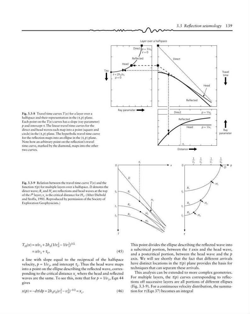
This analysis can be extended to more complex geometries.
For multiple layers, the τ(p) curves corresponding to reflections off successive layers are all portions of different ellipses
(Fig. 3.3-9). For a continuous velocity distribution, the summation for τ (Eqn 37) becomes an integral
Tau
Travel
time
Ray
parameter
Head
Direct
Layer over a halfspace
Reflected
Head
Reflected
Direct
τ = 2h 0 /v 0
p = 0
p = 1/ v 0
τ = 0
Ray parameter
Reflected
Direct
p = 1/v 0
Head
p = 1/v 1
Distance
x c
Fig. 3.3-8 Travel time curves T(x) for a layer over a
halfspace and their representation in the (τ, p) plane.
Each point on the T(x) curves has a slope (ray parameter)
p and intercept τ. The linear travel time curves for the
direct and head waves each map into a point (square and
circle) in the (τ, p) plane. The hyperbolic travel time curve
for the reflection maps into an ellipse in the (τ, p) plane.
Note how an arbitrary point on the reflection’s travel
time curve, marked by the diamond, maps into the other
two curves.
Fig. 3.3-9 Relation between the travel time curve T(x) and the
function τ(p) for multiple layers over a halfspace. D denotes the
direct wave; R i and H i are reflections and head waves at the top
of the i
th layer; x c is the critical distance for H 1 . (After Diebold
and Stoffa, 1981. Reproduced by permission of the Society of
Exploration Geophysicists.)
0
t 0
t 1
t 2
x c
x
R 2
R 3
R 1
H 1
D
T
H 3
H 2
0
t 0
t 1
t 2
p
R 2
H 3
R 1
τ
1
v 3
1
v 2
1
v 1
1
v 0
D
H 2
R 3
H 1
T H (x) = x/v 1 + 2h 0 (1/v 2
0 − 1/v 2
1 ) 1/2
= x/v 1 + τ 1 ,
(45)
a line with slope equal to the reciprocal of the halfspace
velocity, p = 1/v 1 , and intercept τ 1 . Thus the head wave maps
into a point on the ellipse describing the reflected wave, corresponding to the critical distance x c where the head and reflected
waves are the same. To see this, note that for p = 1/v 1 , Eqn 44
gives
x(p) = −dτ/dp = 2h 0 v 0 (v 2
1 − v 2
0 ) −1/2 = x c .
(46)
This point divides the ellipse describing the reflected wave into
a subcritical portion, between the τ axis and the head wave,
and a postcritical portion, between the head wave and the p
axis. We will see shortly that the fact that different arrivals
have distinct locations in the τ(p) plane provides the basis for
techniques that can separate these arrivals.
This analysis can be extended to more complex geometries.
For multiple layers, the τ(p) curves corresponding to reflections off successive layers are all portions of different ellipses
(Fig. 3.3-9). For a continuous velocity distribution, the summation for τ (Eqn 37) becomes an integral
Tau
Travel
time
Ray
parameter
Head
Direct
Layer over a halfspace
Reflected
Head
Reflected
Direct
τ = 2h 0 /v 0
p = 0
p = 1/ v 0
τ = 0
Ray parameter
Reflected
Direct
p = 1/v 0
Head
p = 1/v 1
Distance
x c
Fig. 3.3-8 Travel time curves T(x) for a layer over a
halfspace and their representation in the (τ, p) plane.
Each point on the T(x) curves has a slope (ray parameter)
p and intercept τ. The linear travel time curves for the
direct and head waves each map into a point (square and
circle) in the (τ, p) plane. The hyperbolic travel time curve
for the reflection maps into an ellipse in the (τ, p) plane.
Note how an arbitrary point on the reflection’s travel
time curve, marked by the diamond, maps into the other
two curves.
Fig. 3.3-9 Relation between the travel time curve T(x) and the
function τ(p) for multiple layers over a halfspace. D denotes the
direct wave; R i and H i are reflections and head waves at the top
of the i
th layer; x c is the critical distance for H 1 . (After Diebold
and Stoffa, 1981. Reproduced by permission of the Society of
Exploration Geophysicists.)