

136 Seismology and Earth Structure
Because this was derived for an arbitrary incidence angle,
vertical incidence can be used for simplifications, so in each
layer the travel time equals the one-way vertical travel time,
∆T j = ∆t j , and the total travel time is T = 2 ∑
=
j
n
0
∆t j . Hence
E n
j
j
j
n
j
j
n
v t
t
2
2
0
0
=
⎛
⎝
⎜
⎜
⎞
⎠
⎟
⎟
⎛
⎝
⎜
⎜
⎞
⎠
⎟
⎟
=
=
∑
∑ .
∆
∆
(18)
E n , the appropriate average velocity for the travel time curve, is
the time-weighted root mean square, or rms, velocity for the
first n layers. This hyperbolic approximation and the exact
solutions agree well except for large offsets.
These results let us find the layer velocities from the travel
time curves. Given a reflection from the top of the n th layer,
with vertical two-way travel time t n−1 and rms velocity E n−1 ,
and a reflection from the top of the (n + 1) th layer, with vertical
two-way travel time t n and rms velocity E n , the velocity in the
n th layer is
v
t
t
t
t
n
n n
n
n
n
n
2
2
1
2
1
1
=
−
−
−
−
−
.
E
E
(19)
This relationship is called the Dix equation. 2 The resulting
velocity, called an interval velocity, is better determined for
larger offsets, where the slope of the travel time curve is greater.
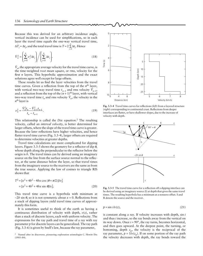
Because the later reflections have higher velocities, and hence
flatter travel time curves (Fig. 3.3-4), larger offsets are required
to determine velocities at greater depths.
Travel time calculations are more complicated for dipping
layers. Figure 3.3-5 shows the geometry for a reflector of dip θ,
whose depth along the perpendicular to the reflector below the
origin is h. The travel times can by derived using an imaginary
source on the line from the surface source normal to the reflector, at the same distance below the layer, so that travel times
from the imaginary source to the receivers are the same as from
the true source. Applying the law of cosines to triangle RIS
shows that
T 2 = [x 2 + 4h 2 − 4hx cos (θ + π/2)]/v 2
0
= [x 2 + 4h 2 + 4hx sin θ]/v 2
0 .
(20)
This travel time curve is a hyperbola with minimum at
−2h sin θ, so it is not symmetric about x = 0. Reflections from
a stack of dipping layers yield travel time curves of approximately this form.
It is sometimes useful to think of the earth as having a
continuous distribution of velocity with depth, v(z), rather
than a stack of discrete layers, each with uniform velocity. The
expressions for the ray path and travel time of a ray with ray
parameter p for discrete layers can be generalized. The ray path
(Fig. 3.3-6) is given by Snell’s law, because the ray parameter,
0
2
4
6
8
10 0
4
8
Distance (km)
5
6
7
8
Velocity (km/s)
5
10
15
20
25
Depth (km)
Time (s)
Fig. 3.3-4 Travel time curves for reflections (left) from a layered structure
(right) corresponding to continental crust. Reflections from deeper
interfaces are flatter, or have shallower slopes, due to the increase of
velocity with depth.
90° +
S
R
x
x
−2h sin θ
t
I
h
h
θ
θ
Fig. 3.3-5 The travel time curve for a reflection off a dipping interface can
be derived using an imaginary source (I) at depth that gives the same travel
times. The resulting hyperbola has a minimum at a nonzero offset. S and
R denote the source and the receiver.
p = sin i /v(z),
(21)
is constant along a ray. If velocity increases with depth, sin i
and thus i increase, so the ray bends away from the vertical on
its way down. Once i = 90°, the ray turns, becomes horizontal,
and then goes upward. At the deepest point, the turning, or
bottoming, depth z p , the velocity is the reciprocal of the
ray parameter, p = 1/v(z p ). If on some portion of the ray path
the velocity decreases with depth, the ray bends toward the
2 Named after its discoverer, pioneering exploration seismologist C. Hewitt Dix
(1905–84).
Because this was derived for an arbitrary incidence angle,
vertical incidence can be used for simplifications, so in each
layer the travel time equals the one-way vertical travel time,
∆T j = ∆t j , and the total travel time is T = 2 ∑
=
j
n
0
∆t j . Hence
E n
j
j
j
n
j
j
n
v t
t
2
2
0
0
=
⎛
⎝
⎜
⎜
⎞
⎠
⎟
⎟
⎛
⎝
⎜
⎜
⎞
⎠
⎟
⎟
=
=
∑
∑ .
∆
∆
(18)
E n , the appropriate average velocity for the travel time curve, is
the time-weighted root mean square, or rms, velocity for the
first n layers. This hyperbolic approximation and the exact
solutions agree well except for large offsets.
These results let us find the layer velocities from the travel
time curves. Given a reflection from the top of the n th layer,
with vertical two-way travel time t n−1 and rms velocity E n−1 ,
and a reflection from the top of the (n + 1) th layer, with vertical
two-way travel time t n and rms velocity E n , the velocity in the
n th layer is
v
t
t
t
t
n
n n
n
n
n
n
2
2
1
2
1
1
=
−
−
−
−
−
.
E
E
(19)
This relationship is called the Dix equation. 2 The resulting
velocity, called an interval velocity, is better determined for
larger offsets, where the slope of the travel time curve is greater.
Because the later reflections have higher velocities, and hence
flatter travel time curves (Fig. 3.3-4), larger offsets are required
to determine velocities at greater depths.
Travel time calculations are more complicated for dipping
layers. Figure 3.3-5 shows the geometry for a reflector of dip θ,
whose depth along the perpendicular to the reflector below the
origin is h. The travel times can by derived using an imaginary
source on the line from the surface source normal to the reflector, at the same distance below the layer, so that travel times
from the imaginary source to the receivers are the same as from
the true source. Applying the law of cosines to triangle RIS
shows that
T 2 = [x 2 + 4h 2 − 4hx cos (θ + π/2)]/v 2
0
= [x 2 + 4h 2 + 4hx sin θ]/v 2
0 .
(20)
This travel time curve is a hyperbola with minimum at
−2h sin θ, so it is not symmetric about x = 0. Reflections from
a stack of dipping layers yield travel time curves of approximately this form.
It is sometimes useful to think of the earth as having a
continuous distribution of velocity with depth, v(z), rather
than a stack of discrete layers, each with uniform velocity. The
expressions for the ray path and travel time of a ray with ray
parameter p for discrete layers can be generalized. The ray path
(Fig. 3.3-6) is given by Snell’s law, because the ray parameter,
0
2
4
6
8
10 0
4
8
Distance (km)
5
6
7
8
Velocity (km/s)
5
10
15
20
25
Depth (km)
Time (s)
Fig. 3.3-4 Travel time curves for reflections (left) from a layered structure
(right) corresponding to continental crust. Reflections from deeper
interfaces are flatter, or have shallower slopes, due to the increase of
velocity with depth.
90° +
S
R
x
x
−2h sin θ
t
I
h
h
θ
θ
Fig. 3.3-5 The travel time curve for a reflection off a dipping interface can
be derived using an imaginary source (I) at depth that gives the same travel
times. The resulting hyperbola has a minimum at a nonzero offset. S and
R denote the source and the receiver.
p = sin i /v(z),
(21)
is constant along a ray. If velocity increases with depth, sin i
and thus i increase, so the ray bends away from the vertical on
its way down. Once i = 90°, the ray turns, becomes horizontal,
and then goes upward. At the deepest point, the turning, or
bottoming, depth z p , the velocity is the reciprocal of the
ray parameter, p = 1/v(z p ). If on some portion of the ray path
the velocity decreases with depth, the ray bends toward the
2 Named after its discoverer, pioneering exploration seismologist C. Hewitt Dix
(1905–84).