

134 Seismology and Earth Structure
an argument against eclogite being a major component of the
upper mantle is that, by contrast with peridotite, it does not
contain olivine and would not yield the observed anisotropic P n
velocities. However, the gabbro-to-eclogite transformation
may occur in subducting slabs (Section 5.4.2) and play a role in
causing earthquakes there.
3.3 Reflection seismology
In the last section, we concentrated on the use of refracted
arrivals to infer velocity structure with depth, and noted that
reflected arrivals also contain valuable information for this
purpose. Studies using the reflected arrivals, known as reflection seismology, determine velocities within the crust, and
thus are essential in oil and gas exploration. As a result, data
acquisition and processing methods have often been developed
first by reflection seismologists. For example, digital data were
generally used in exploration before they became common
in earthquake studies. Similarly, because reflection data are
densely sampled in space and time, and the mathematics of
wave propagation in a layered medium is simpler than for
a spherical earth, techniques are often first developed with
reflection data. In this section we survey basic concepts in
reflection seismology, some of which we later apply to earthquakes and the spherical earth.
3.3.1 Travel time curves for reflections
We first consider the simplest geometry: a flat layer of uniformvelocity material underlain by a halfspace with a higher
velocity (Fig. 3.2-1). Although most applications use P waves,
we write the velocity as “v” because the results also apply to
S waves. For a layer of thickness h 0 with velocity v 0 , we saw
in Section 3.2.2 that the travel time as a function of source-toreceiver distance, known as offset in reflection seismology, is
T(x) 2 = x 2 /v 2
0 + 4h 2
0 /v 2
0 = x 2 /v 2
0 + t 2
0 .
(1)
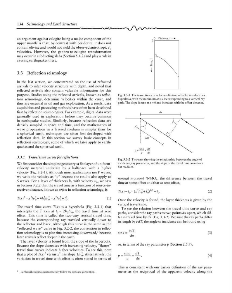
The travel time curve T(x) is a hyperbola (Fig. 3.3-1) that
intercepts the T axis at t 0 = 2h 0 /v 0 , the travel time at zero
offset. This time is called the two-way vertical travel time,
because the corresponding ray traveled vertically down to
the reflector and back. Although this curve is the same as the
“reflected wave” curve in Fig. 3.2-2, the convention in reflection seismology is to plot time increasing downward, 1 because
later arrivals reflect deeper in the earth.
The layer velocity is found from the slope of the hyperbola.
Because the slope decreases with increasing velocity, “flatter”
travel time curves indicate higher velocities. To see this, note
that a plot of T(x) 2 versus x 2 has slope 1/v 2
0 . Alternatively, the
variation in travel time with offset is often stated in terms of
1 Earthquake seismologists generally follow the opposite convention.
Distance, x
t 0
0
0
Time, t
Fig. 3.3-1 The travel time curve for a reflection off a flat interface is a
hyperbola, with the minimum at x = 0 corresponding to a vertical ray
path. The slope is zero at x = 0 and increases with the offset distance.
Fig. 3.3-2 Two rays showing the relationship between the angle of
incidence, ray parameter, and the slope of the travel time curve for a
flat medium.
dx
i
vdT
i
p =
sin i
v
=
dT
dx
normal moveout (NMO), the difference between the travel
time at some offset and that at zero offset,
T(x) − t 0 = (x 2 /v 2
0 + t 2
0 ) 1/2 − t 0 .
(2)
Once the velocity is found, the layer thickness is given by the
vertical travel time.
To see the relation between the travel time curve and ray
paths, consider the ray paths to two points dx apart, which differ in travel time by dT (Fig. 3.3-2). Because the ray paths differ
in length by vdT, the angle of incidence can be found using
sin i
vdT
dx
=
(3)
or, in terms of the ray parameter p (Section 2.5.7),
p
i
v
dT
dx
sin
.
=
=
(4)
This is consistent with our earlier definition of the ray parameter as the reciprocal of the apparent velocity along the
an argument against eclogite being a major component of the
upper mantle is that, by contrast with peridotite, it does not
contain olivine and would not yield the observed anisotropic P n
velocities. However, the gabbro-to-eclogite transformation
may occur in subducting slabs (Section 5.4.2) and play a role in
causing earthquakes there.
3.3 Reflection seismology
In the last section, we concentrated on the use of refracted
arrivals to infer velocity structure with depth, and noted that
reflected arrivals also contain valuable information for this
purpose. Studies using the reflected arrivals, known as reflection seismology, determine velocities within the crust, and
thus are essential in oil and gas exploration. As a result, data
acquisition and processing methods have often been developed
first by reflection seismologists. For example, digital data were
generally used in exploration before they became common
in earthquake studies. Similarly, because reflection data are
densely sampled in space and time, and the mathematics of
wave propagation in a layered medium is simpler than for
a spherical earth, techniques are often first developed with
reflection data. In this section we survey basic concepts in
reflection seismology, some of which we later apply to earthquakes and the spherical earth.
3.3.1 Travel time curves for reflections
We first consider the simplest geometry: a flat layer of uniformvelocity material underlain by a halfspace with a higher
velocity (Fig. 3.2-1). Although most applications use P waves,
we write the velocity as “v” because the results also apply to
S waves. For a layer of thickness h 0 with velocity v 0 , we saw
in Section 3.2.2 that the travel time as a function of source-toreceiver distance, known as offset in reflection seismology, is
T(x) 2 = x 2 /v 2
0 + 4h 2
0 /v 2
0 = x 2 /v 2
0 + t 2
0 .
(1)
The travel time curve T(x) is a hyperbola (Fig. 3.3-1) that
intercepts the T axis at t 0 = 2h 0 /v 0 , the travel time at zero
offset. This time is called the two-way vertical travel time,
because the corresponding ray traveled vertically down to
the reflector and back. Although this curve is the same as the
“reflected wave” curve in Fig. 3.2-2, the convention in reflection seismology is to plot time increasing downward, 1 because
later arrivals reflect deeper in the earth.
The layer velocity is found from the slope of the hyperbola.
Because the slope decreases with increasing velocity, “flatter”
travel time curves indicate higher velocities. To see this, note
that a plot of T(x) 2 versus x 2 has slope 1/v 2
0 . Alternatively, the
variation in travel time with offset is often stated in terms of
1 Earthquake seismologists generally follow the opposite convention.
Distance, x
t 0
0
0
Time, t
Fig. 3.3-1 The travel time curve for a reflection off a flat interface is a
hyperbola, with the minimum at x = 0 corresponding to a vertical ray
path. The slope is zero at x = 0 and increases with the offset distance.
Fig. 3.3-2 Two rays showing the relationship between the angle of
incidence, ray parameter, and the slope of the travel time curve for a
flat medium.
dx
i
vdT
i
p =
sin i
v
=
dT
dx
normal moveout (NMO), the difference between the travel
time at some offset and that at zero offset,
T(x) − t 0 = (x 2 /v 2
0 + t 2
0 ) 1/2 − t 0 .
(2)
Once the velocity is found, the layer thickness is given by the
vertical travel time.
To see the relation between the travel time curve and ray
paths, consider the ray paths to two points dx apart, which differ in travel time by dT (Fig. 3.3-2). Because the ray paths differ
in length by vdT, the angle of incidence can be found using
sin i
vdT
dx
=
(3)
or, in terms of the ray parameter p (Section 2.5.7),
p
i
v
dT
dx
sin
.
=
=
(4)
This is consistent with our earlier definition of the ray parameter as the reciprocal of the apparent velocity along the