

Source
Receiver
v 0
v 1
x
i c
h d
h d
i c
θ
θ
h d ta n i c
(h d + x si n ) ta n i c
θ
x si n θ
Travel time
Direct
H 1
H 2
R 1
Distance
D
H 1
H 2
R 2
R 1
v 2
v 1 , h 1
v 0 , h 0
τ 2
τ 1
R 2
3.2 Refraction seismology 125
Time
Distance
Slope = 1/v 3
Slope = 1/v 2
Slope = 1/v 0
Source
Receiver
v 0
v 1
v 2
v 3
No head wave
Time
Distance
Slope = 1/v 1
Slope = 1/v 2
Slope = 1/v 0
Source
Receiver
v 0
v 1
v 2
Layer 1
Layer 2
For the flat case, (θ = 0), this is just Eqn 4. Simplifying using
Eqns 5 and 7 yields
T x
x
i
v
h
x
i
v
i
d
c
d
c
c
( )
cos sin
(
sin )(
sin )
cos
=
+
+
−
θ
θ
0
2
0
2
1
=
+
+
=
+
sin (
)
cos
,
x
i
v
h
i
v
x
v
c
d
c
d
d
θ
τ
0
0
2
(16)
which is a straight line with slope 1/v d and intercept τ d .
Similarly, the travel time for the head wave in the up-dip
direction is
T x
x
i
v
h
i
v
x
v
u
c
u
c
u
u
( )
sin (
)
cos
,
=
−
+
=
+
θ
τ
0
0
2
(17)
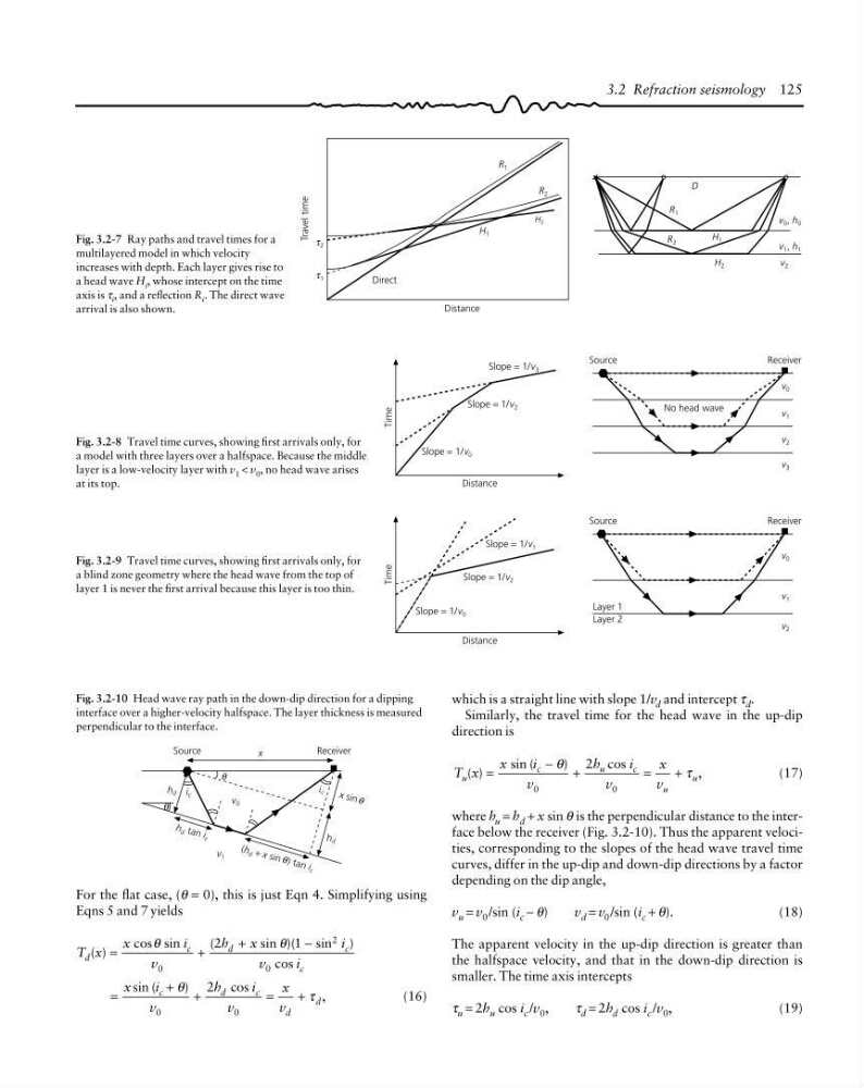
where h u = h d + x sin θ is the perpendicular distance to the interface below the receiver (Fig. 3.2-10). Thus the apparent velocities, corresponding to the slopes of the head wave travel time
curves, differ in the up-dip and down-dip directions by a factor
depending on the dip angle,
v u = v 0 /sin (i c − θ)
v d = v 0 /sin (i c + θ).
(18)
The apparent velocity in the up-dip direction is greater than
the halfspace velocity, and that in the down-dip direction is
smaller. The time axis intercepts
τ u = 2h u cos i c /v 0 ,
τ d = 2h d cos i c /v 0 ,
(19)
Fig. 3.2-7 Ray paths and travel times for a
multilayered model in which velocity
increases with depth. Each layer gives rise to
a head wave H i , whose intercept on the time
axis is τ i , and a reflection R i . The direct wave
arrival is also shown.
Fig. 3.2-8 Travel time curves, showing first arrivals only, for
a model with three layers over a halfspace. Because the middle
layer is a low-velocity layer with v 1 < v 0 , no head wave arises
at its top.
Fig. 3.2-10 Head wave ray path in the down-dip direction for a dipping
interface over a higher-velocity halfspace. The layer thickness is measured
perpendicular to the interface.
Fig. 3.2-9 Travel time curves, showing first arrivals only, for
a blind zone geometry where the head wave from the top of
layer 1 is never the first arrival because this layer is too thin.
Receiver
v 0
v 1
x
i c
h d
h d
i c
θ
θ
h d ta n i c
(h d + x si n ) ta n i c
θ
x si n θ
Travel time
Direct
H 1
H 2
R 1
Distance
D
H 1
H 2
R 2
R 1
v 2
v 1 , h 1
v 0 , h 0
τ 2
τ 1
R 2
3.2 Refraction seismology 125
Time
Distance
Slope = 1/v 3
Slope = 1/v 2
Slope = 1/v 0
Source
Receiver
v 0
v 1
v 2
v 3
No head wave
Time
Distance
Slope = 1/v 1
Slope = 1/v 2
Slope = 1/v 0
Source
Receiver
v 0
v 1
v 2
Layer 1
Layer 2
For the flat case, (θ = 0), this is just Eqn 4. Simplifying using
Eqns 5 and 7 yields
T x
x
i
v
h
x
i
v
i
d
c
d
c
c
( )
cos sin
(
sin )(
sin )
cos
=
+
+
−
θ
θ
0
2
0
2
1
=
+
+
=
+
sin (
)
cos
,
x
i
v
h
i
v
x
v
c
d
c
d
d
θ
τ
0
0
2
(16)
which is a straight line with slope 1/v d and intercept τ d .
Similarly, the travel time for the head wave in the up-dip
direction is
T x
x
i
v
h
i
v
x
v
u
c
u
c
u
u
( )
sin (
)
cos
,
=
−
+
=
+
θ
τ
0
0
2
(17)
where h u = h d + x sin θ is the perpendicular distance to the interface below the receiver (Fig. 3.2-10). Thus the apparent velocities, corresponding to the slopes of the head wave travel time
curves, differ in the up-dip and down-dip directions by a factor
depending on the dip angle,
v u = v 0 /sin (i c − θ)
v d = v 0 /sin (i c + θ).
(18)
The apparent velocity in the up-dip direction is greater than
the halfspace velocity, and that in the down-dip direction is
smaller. The time axis intercepts
τ u = 2h u cos i c /v 0 ,
τ d = 2h d cos i c /v 0 ,
(19)
Fig. 3.2-7 Ray paths and travel times for a
multilayered model in which velocity
increases with depth. Each layer gives rise to
a head wave H i , whose intercept on the time
axis is τ i , and a reflection R i . The direct wave
arrival is also shown.
Fig. 3.2-8 Travel time curves, showing first arrivals only, for
a model with three layers over a halfspace. Because the middle
layer is a low-velocity layer with v 1 < v 0 , no head wave arises
at its top.
Fig. 3.2-10 Head wave ray path in the down-dip direction for a dipping
interface over a higher-velocity halfspace. The layer thickness is measured
perpendicular to the interface.
Fig. 3.2-9 Travel time curves, showing first arrivals only, for
a blind zone geometry where the head wave from the top of
layer 1 is never the first arrival because this layer is too thin.