

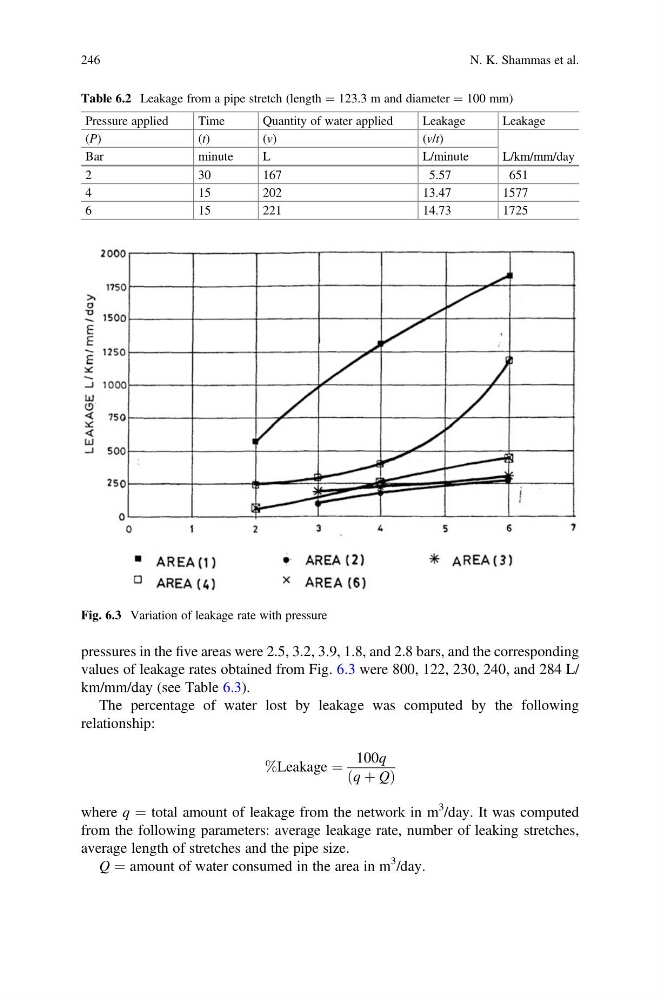
pressures in the five areas were 2.5, 3.2, 3.9, 1.8, and 2.8 bars, and the corresponding
values of leakage rates obtained from Fig. 6.3 were 800, 122, 230, 240, and 284 L/
km/mm/day (see Table 6.3).
The percentage of water lost by leakage was computed by the following
relationship:
%Leakage ¼
100q
q þ Q
ð
Þ
where q ¼ total amount of leakage from the network in m
3 /day. It was computed
from the following parameters: average leakage rate, number of leaking stretches,
average length of stretches and the pipe size.
Q ¼ amount of water consumed in the area in m
3 /day.
Table 6.2 Leakage from a pipe stretch (length ¼ 123.3 m and diameter ¼ 100 mm)
Pressure applied
Time
Quantity of water applied
Leakage
Leakage
(P)
( t)
( v)
( v/t)
L/km/mm/day
Bar
minute
L
L/minute
2
30
167
5.57
651
4
15
202
13.47
1577
6
15
221
14.73
1725
Fig. 6.3 Variation of leakage rate with pressure
246
N. K. Shammas et al.
values of leakage rates obtained from Fig. 6.3 were 800, 122, 230, 240, and 284 L/
km/mm/day (see Table 6.3).
The percentage of water lost by leakage was computed by the following
relationship:
%Leakage ¼
100q
q þ Q
ð
Þ
where q ¼ total amount of leakage from the network in m
3 /day. It was computed
from the following parameters: average leakage rate, number of leaking stretches,
average length of stretches and the pipe size.
Q ¼ amount of water consumed in the area in m
3 /day.
Table 6.2 Leakage from a pipe stretch (length ¼ 123.3 m and diameter ¼ 100 mm)
Pressure applied
Time
Quantity of water applied
Leakage
Leakage
(P)
( t)
( v)
( v/t)
L/km/mm/day
Bar
minute
L
L/minute
2
30
167
5.57
651
4
15
202
13.47
1577
6
15
221
14.73
1725
Fig. 6.3 Variation of leakage rate with pressure
246
N. K. Shammas et al.