

incidence of the electromagnetic radiation (φ i
1 ) is given with respect to the surface
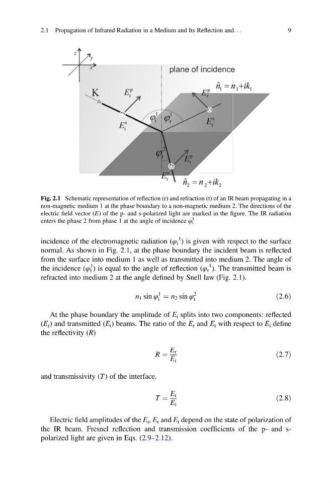
normal. As shown in Fig. 2.1, at the phase boundary the incident beam is reflected
from the surface into medium 1 as well as transmitted into medium 2. The angle of
the incidence (φ i
1 ) is equal to the angle of reflection (φ r
1 ). The transmitted beam is
refracted into medium 2 at the angle defined by Snell law (Fig. 2.1).
n 1 sin φ
1
i ¼ n 2 sin φ
2
t
ð2:6Þ
At the phase boundary the amplitude of E i splits into two components: reflected
(E r ) and transmitted (E t ) beams. The ratio of the E r and E t with respect to E i define
the reflectivity (R)
R ¼
E r
E i
ð2:7Þ
and transmissivity (T ) of the interface.
T ¼
E t
E i
ð2:8Þ
Electric field amplitudes of the E i , E r and E t depend on the state of polarization of
the IR beam. Fresnel reflection and transmission coefficients of the p- and spolarized light are given in Eqs. (2.9–2.12).
Fig. 2.1 Schematic representation of reflection (r) and refraction (t) of an IR beam propagating in a
non-magnetic medium 1 at the phase boundary to a non-magnetic medium 2. The directions of the
electric field vector (E) of the p- and s-polarized light are marked in the figure. The IR radiation
enters the phase 2 from phase 1 at the angle of incidence φ i
1
2.1 Propagation of Infrared Radiation in a Medium and Its Reflection and. . .
9
1 ) is given with respect to the surface
normal. As shown in Fig. 2.1, at the phase boundary the incident beam is reflected
from the surface into medium 1 as well as transmitted into medium 2. The angle of
the incidence (φ i
1 ) is equal to the angle of reflection (φ r
1 ). The transmitted beam is
refracted into medium 2 at the angle defined by Snell law (Fig. 2.1).
n 1 sin φ
1
i ¼ n 2 sin φ
2
t
ð2:6Þ
At the phase boundary the amplitude of E i splits into two components: reflected
(E r ) and transmitted (E t ) beams. The ratio of the E r and E t with respect to E i define
the reflectivity (R)
R ¼
E r
E i
ð2:7Þ
and transmissivity (T ) of the interface.
T ¼
E t
E i
ð2:8Þ
Electric field amplitudes of the E i , E r and E t depend on the state of polarization of
the IR beam. Fresnel reflection and transmission coefficients of the p- and spolarized light are given in Eqs. (2.9–2.12).
Fig. 2.1 Schematic representation of reflection (r) and refraction (t) of an IR beam propagating in a
non-magnetic medium 1 at the phase boundary to a non-magnetic medium 2. The directions of the
electric field vector (E) of the p- and s-polarized light are marked in the figure. The IR radiation
enters the phase 2 from phase 1 at the angle of incidence φ i
1
2.1 Propagation of Infrared Radiation in a Medium and Its Reflection and. . .
9