

D. Phase IV landfill
The existing percolate treatment unit has a design capacity of 1500 m
3 /d in the
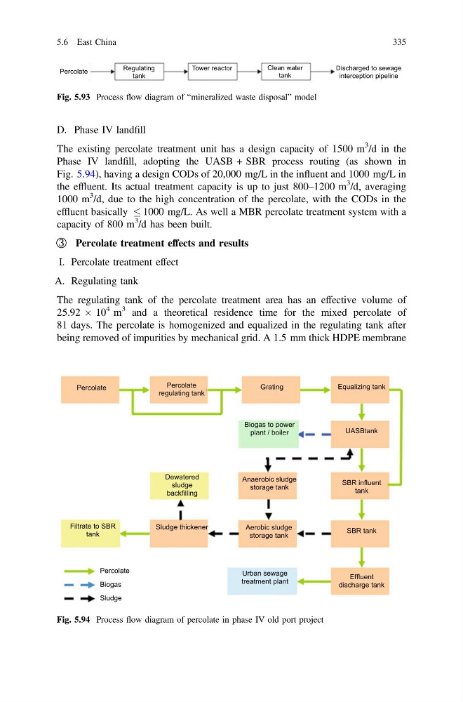
Phase IV landfill, adopting the UASB + SBR process routing (as shown in
Fig. 5.94), having a design CODs of 20,000 mg/L in the influent and 1000 mg/L in
the effluent. Its actual treatment capacity is up to just 800–1200 m
3 /d, averaging
1000 m
3 /d, due to the high concentration of the percolate, with the CODs in the
effluent basically 1000 mg/L. As well a MBR percolate treatment system with a
capacity of 800 m
3 /d has been built.
③ Percolate treatment effects and results
I. Percolate treatment effect
A. Regulating tank
The regulating tank of the percolate treatment area has an effective volume of
25.92 Â 10
4 m
3 and a theoretical residence time for the mixed percolate of
81 days. The percolate is homogenized and equalized in the regulating tank after
being removed of impurities by mechanical grid. A 1.5 mm thick HDPE membrane
Percolate
Regulating
tank
Tower reactor
Clean water
tank
Discharged to sewage
interception pipeline
Fig. 5.93 Process flow diagram of “mineralized waste disposal” model
Percolate
Percolate
regulating tank
Grating
Equalizing tank
Biogas to power
plant / boiler
UASBtank
Dewatered
sludge
backfilling
Anaerobic sludge
storage tank
SBR influent
tank
Filtrate to SBR
tank
Sludge thickener
Aerobic sludge
storage tank
SBR tank
Urban sewage
treatment plant
Effluent
discharge tank
Percolate
Biogas
Sludge
Fig. 5.94 Process flow diagram of percolate in phase IV old port project
5.6 East China
335
The existing percolate treatment unit has a design capacity of 1500 m
3 /d in the
Phase IV landfill, adopting the UASB + SBR process routing (as shown in
Fig. 5.94), having a design CODs of 20,000 mg/L in the influent and 1000 mg/L in
the effluent. Its actual treatment capacity is up to just 800–1200 m
3 /d, averaging
1000 m
3 /d, due to the high concentration of the percolate, with the CODs in the
effluent basically 1000 mg/L. As well a MBR percolate treatment system with a
capacity of 800 m
3 /d has been built.
③ Percolate treatment effects and results
I. Percolate treatment effect
A. Regulating tank
The regulating tank of the percolate treatment area has an effective volume of
25.92 Â 10
4 m
3 and a theoretical residence time for the mixed percolate of
81 days. The percolate is homogenized and equalized in the regulating tank after
being removed of impurities by mechanical grid. A 1.5 mm thick HDPE membrane
Percolate
Regulating
tank
Tower reactor
Clean water
tank
Discharged to sewage
interception pipeline
Fig. 5.93 Process flow diagram of “mineralized waste disposal” model
Percolate
Percolate
regulating tank
Grating
Equalizing tank
Biogas to power
plant / boiler
UASBtank
Dewatered
sludge
backfilling
Anaerobic sludge
storage tank
SBR influent
tank
Filtrate to SBR
tank
Sludge thickener
Aerobic sludge
storage tank
SBR tank
Urban sewage
treatment plant
Effluent
discharge tank
Percolate
Biogas
Sludge
Fig. 5.94 Process flow diagram of percolate in phase IV old port project
5.6 East China
335