

layer with a cutting ring, and flatten both ends of the sample. Repeated application
with a soil-finishing cutter is prohibited. Put it into a saturator and pump it to
saturation. Put the cutting ring containing the sample into the casing and install the
water-proof washers at different positions. Pay attention to the porous stones and
filter paper on the upper and lower parts of the sample, install them in sequence,
cover the top cover, and tighten the top screws without water and air leakage.
Connect the permeameter inlet containing the sample to the head device
(piezometer). Use pure water in the water supply bottle to fill the water inlet pipe
with water and permeate into the infiltration container; open the vent valve to drain
the air at the bottom of the infiltration container until there is no bubble in the
overflow water; close the drain valve, lay flat the infiltration container, and close the
water inlet pipe clamp.
Before permeating into the sample, discharge from the bottom air bleed valve
first. When the bottom air is removed until there is no air bubble in the air bleed
valve, the air bleed valve will be closed and water will flow from bottom to top and
be discharged from the top water outlet pipe. Inject pure water into the variable
head pipe. The water head height shall be determined according to the looseness
degree of the sample structure and usually not more than 2 m. Cut off the water
source after the water level remains stable and open the water inlet pipe clamp to
allow the water to pass through the sample. When water overflows from the outlet,
measure and record the height and start time of the starting head in the variable head
pipe, measure and record the changes of the head and time at predetermined time
intervals, and measure and record the water temperature of the outlet. Change the
height of the water level in the variable head pipe, measure and record the changes
of the head and time after the water level remains stable, repeat it for 5–6 times, and
Rigid
landfill pit
Legend
Perched water
Phreatic-confined water
Confined water
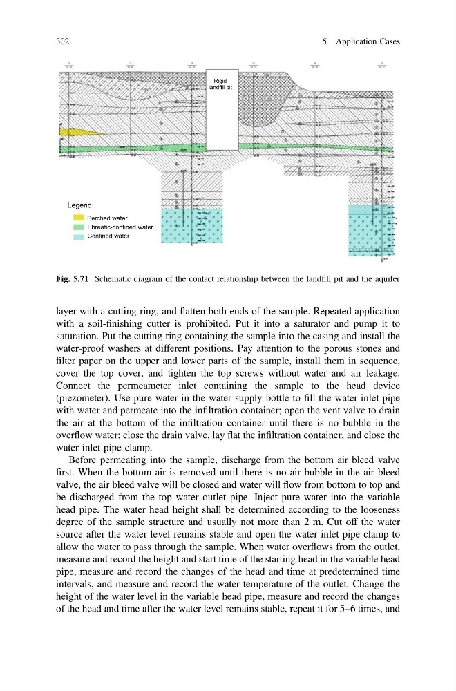
Fig. 5.71 Schematic diagram of the contact relationship between the landfill pit and the aquifer
302
5 Application Cases
with a soil-finishing cutter is prohibited. Put it into a saturator and pump it to
saturation. Put the cutting ring containing the sample into the casing and install the
water-proof washers at different positions. Pay attention to the porous stones and
filter paper on the upper and lower parts of the sample, install them in sequence,
cover the top cover, and tighten the top screws without water and air leakage.
Connect the permeameter inlet containing the sample to the head device
(piezometer). Use pure water in the water supply bottle to fill the water inlet pipe
with water and permeate into the infiltration container; open the vent valve to drain
the air at the bottom of the infiltration container until there is no bubble in the
overflow water; close the drain valve, lay flat the infiltration container, and close the
water inlet pipe clamp.
Before permeating into the sample, discharge from the bottom air bleed valve
first. When the bottom air is removed until there is no air bubble in the air bleed
valve, the air bleed valve will be closed and water will flow from bottom to top and
be discharged from the top water outlet pipe. Inject pure water into the variable
head pipe. The water head height shall be determined according to the looseness
degree of the sample structure and usually not more than 2 m. Cut off the water
source after the water level remains stable and open the water inlet pipe clamp to
allow the water to pass through the sample. When water overflows from the outlet,
measure and record the height and start time of the starting head in the variable head
pipe, measure and record the changes of the head and time at predetermined time
intervals, and measure and record the water temperature of the outlet. Change the
height of the water level in the variable head pipe, measure and record the changes
of the head and time after the water level remains stable, repeat it for 5–6 times, and
Rigid
landfill pit
Legend
Perched water
Phreatic-confined water
Confined water
Fig. 5.71 Schematic diagram of the contact relationship between the landfill pit and the aquifer
302
5 Application Cases