

438
G. Osada et al.
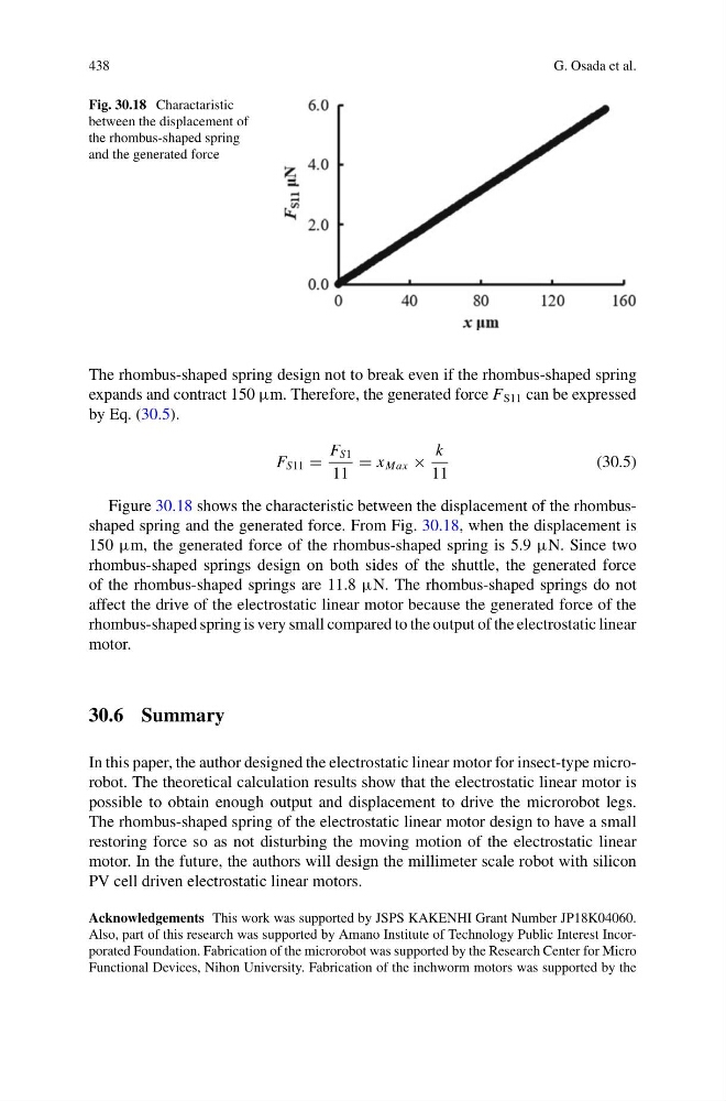
Fig. 30.18 Charactaristic
between the displacement of
the rhombus-shaped spring
and the generated force
The rhombus-shaped spring design not to break even if the rhombus-shaped spring
expands and contract 150 µm. Therefore, the generated force F S11 can be expressed
by Eq. (30.5).
F S11 =
F S1
11
= x Max ×
k
11
(30.5)
Figure 30.18 shows the characteristic between the displacement of the rhombusshaped spring and the generated force. From Fig. 30.18, when the displacement is
150 µm, the generated force of the rhombus-shaped spring is 5.9 µN. Since two
rhombus-shaped springs design on both sides of the shuttle, the generated force
of the rhombus-shaped springs are 11.8 µN. The rhombus-shaped springs do not
affect the drive of the electrostatic linear motor because the generated force of the
rhombus-shaped spring is very small compared to the output of the electrostatic linear
motor.
30.6 Summary
In this paper, the author designed the electrostatic linear motor for insect-type microrobot. The theoretical calculation results show that the electrostatic linear motor is
possible to obtain enough output and displacement to drive the microrobot legs.
The rhombus-shaped spring of the electrostatic linear motor design to have a small
restoring force so as not disturbing the moving motion of the electrostatic linear
motor. In the future, the authors will design the millimeter scale robot with silicon
PV cell driven electrostatic linear motors.
Acknowledgements This work was supported by JSPS KAKENHI Grant Number JP18K04060.
Also, part of this research was supported by Amano Institute of Technology Public Interest Incorporated Foundation. Fabrication of the microrobot was supported by the Research Center for Micro
Functional Devices, Nihon University. Fabrication of the inchworm motors was supported by the
G. Osada et al.
Fig. 30.18 Charactaristic
between the displacement of
the rhombus-shaped spring
and the generated force
The rhombus-shaped spring design not to break even if the rhombus-shaped spring
expands and contract 150 µm. Therefore, the generated force F S11 can be expressed
by Eq. (30.5).
F S11 =
F S1
11
= x Max ×
k
11
(30.5)
Figure 30.18 shows the characteristic between the displacement of the rhombusshaped spring and the generated force. From Fig. 30.18, when the displacement is
150 µm, the generated force of the rhombus-shaped spring is 5.9 µN. Since two
rhombus-shaped springs design on both sides of the shuttle, the generated force
of the rhombus-shaped springs are 11.8 µN. The rhombus-shaped springs do not
affect the drive of the electrostatic linear motor because the generated force of the
rhombus-shaped spring is very small compared to the output of the electrostatic linear
motor.
30.6 Summary
In this paper, the author designed the electrostatic linear motor for insect-type microrobot. The theoretical calculation results show that the electrostatic linear motor is
possible to obtain enough output and displacement to drive the microrobot legs.
The rhombus-shaped spring of the electrostatic linear motor design to have a small
restoring force so as not disturbing the moving motion of the electrostatic linear
motor. In the future, the authors will design the millimeter scale robot with silicon
PV cell driven electrostatic linear motors.
Acknowledgements This work was supported by JSPS KAKENHI Grant Number JP18K04060.
Also, part of this research was supported by Amano Institute of Technology Public Interest Incorporated Foundation. Fabrication of the microrobot was supported by the Research Center for Micro
Functional Devices, Nihon University. Fabrication of the inchworm motors was supported by the