

436
G. Osada et al.
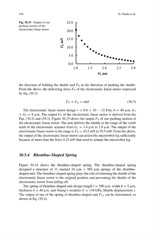
Fig. 30.15 Output of one
pushing motion of the
electrostatic linear motor
the direction of holding the shuttle and F P in the direction of pushing the shuttle.
From the above, the delivering force F P of the electrostatic linear motor expressed
by Eq. (30.3).
F P = F A × sinθ
(30.3)
The electrostatic linear motor design ε = 8.8 × 10 − 12 F/m, h = 40 µm, G 1
+ G 2 = 8 µm. The output F P of the electrostatic linear motor is derived from the
Eqs. (30.2) and (30.3). Figure 30.15 shows the output F P of one pushing motion of
the electrostatic linear motor. The arm delivers the shuttle in the range of the comb
teeth of the electrostatic actuator from G 1 = 1.4 µm to 1.0 µm. The output of the
electrostatic linear motor in the range is F P = 10.2 mN to 20.5 mN. From the above,
the output of the electrostatic linear motor can action the microrobot leg sufficiently
because of more than the force 0.25 mN that need to actuate the microrobot leg.
30.5.4 Rhombus-Shaped Spring
Figure 30.16 shows the rhombus-shaped spring. The rhombus-shaped spring
designed a structure of 11 stacked 34 µm × 985 µm springs of the rhombusshaped unit. The rhombus-shaped spring plays the role of returning the shuttle of the
electrostatic linear motor to the original position and preventing the shuttle of the
electrostatic motor from falling off.
The spring of rhombus-shaped unit design length l = 500 µm, width b = 5 µm,
thickness h = 40 µm, and Young’s modulus E = 130 GPa, Shuttle displacement x.
The output of one of the spring of rhombus-shaped unit F S1 can be determined, as
shown in Eq. (30.4).
G. Osada et al.
Fig. 30.15 Output of one
pushing motion of the
electrostatic linear motor
the direction of holding the shuttle and F P in the direction of pushing the shuttle.
From the above, the delivering force F P of the electrostatic linear motor expressed
by Eq. (30.3).
F P = F A × sinθ
(30.3)
The electrostatic linear motor design ε = 8.8 × 10 − 12 F/m, h = 40 µm, G 1
+ G 2 = 8 µm. The output F P of the electrostatic linear motor is derived from the
Eqs. (30.2) and (30.3). Figure 30.15 shows the output F P of one pushing motion of
the electrostatic linear motor. The arm delivers the shuttle in the range of the comb
teeth of the electrostatic actuator from G 1 = 1.4 µm to 1.0 µm. The output of the
electrostatic linear motor in the range is F P = 10.2 mN to 20.5 mN. From the above,
the output of the electrostatic linear motor can action the microrobot leg sufficiently
because of more than the force 0.25 mN that need to actuate the microrobot leg.
30.5.4 Rhombus-Shaped Spring
Figure 30.16 shows the rhombus-shaped spring. The rhombus-shaped spring
designed a structure of 11 stacked 34 µm × 985 µm springs of the rhombusshaped unit. The rhombus-shaped spring plays the role of returning the shuttle of the
electrostatic linear motor to the original position and preventing the shuttle of the
electrostatic motor from falling off.
The spring of rhombus-shaped unit design length l = 500 µm, width b = 5 µm,
thickness h = 40 µm, and Young’s modulus E = 130 GPa, Shuttle displacement x.
The output of one of the spring of rhombus-shaped unit F S1 can be determined, as
shown in Eq. (30.4).