

420
N. Shimoi
29.3.2 Stability with High Current FE Property of SWCNTs
The utilization of high crystallized SWCNTs to construct an effective cathode
element—with both a low FE fluctuation and stable FE current—relies on the ability
to disperse them uniformly in liquid media. A solvent with In 2 O 3 -SnO 2 (tin-doped
indium oxide; ITO) precursor as the conductive matrix material for the dispersion of high crystallized SWCNTs was used to construct a thin film containing
the well-dispersed SWCNTs. The mixture of SWCNTs, the solvent including the
ITO precursor and a non-ionic dispersant to disperse the SWCNTs was employed to
provide an impact buffer product, following the stepwise dispersing and buffering of
the large impact force generated by ultra-sonication using a homogenizer to receive
the impact. After sintering a film coated with the mixture in a vacuum, the thin film
was activated by scratching the film with a thin metal rod appropriately to obtain
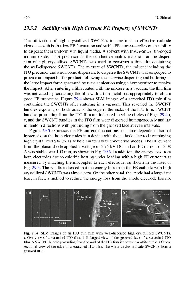
good FE properties. Figure 29.4 shows SEM images of a scratched ITO thin film
containing the SWCNTs after sintering in a vacuum. This revealed the SWCNT
bundles exposing on both sides of the edge in the nicks of the ITO film. SWCNT
bundles protruding from the ITO film are indicated in white circles of Figs. 29.4b,
c, and the SWCNT bundles in the ITO film were dispersed homogeneously and lay
in random directions with protruding from the grooved face at even intervals.
Figure 29.5 expresses the FE current fluctuations and time-dependent thermal
hysteresis on the both electrodes in a device with the cathode electrode employing
high crystallized SWCNTs as field emitters with conductive anodes. The FE current
from the planar diode applied a voltage of 2.75 kV DC and an FE current of 3.08
A was stable over 100 min, as shown in Fig. 29.5. In addition, the energy loss from
both electrodes due to calorific heating under loading with a high FE current was
measured by attaching thermocouples to each electrode, as shown in the inset of
Fig. 29.5. The results indicated that the energy loss from the FE cathode with high
crystallized SWCNTs was almost zero. On the other hand, the anode had a large heat
loss; in fact, a method to reduce the energy loss from the anode electrode has not
200 µm
ITO thin film with
SWCNTs
Protruded
SWCNT bundle
Protruded
SWCNT bundle
(a)
1µm
1µm
(b)
(c)
ITO thin film with SWCNTs
Nicks
Nick
ITO thin film with
SWCNTs
Fig. 29.4 SEM images of an ITO thin film with well-dispersed high crystallized SWCNTs.
a Overview of a scratched ITO film. b Enlarged view of the grooved face of a scratched ITO
film. A SWCNT bundle protruding from the wall of the ITO film is shown in a white circle. c Crosssectional view of the edge of a scratched ITO film. The white circles indicate SWCNTs from a
grooved face
N. Shimoi
29.3.2 Stability with High Current FE Property of SWCNTs
The utilization of high crystallized SWCNTs to construct an effective cathode
element—with both a low FE fluctuation and stable FE current—relies on the ability
to disperse them uniformly in liquid media. A solvent with In 2 O 3 -SnO 2 (tin-doped
indium oxide; ITO) precursor as the conductive matrix material for the dispersion of high crystallized SWCNTs was used to construct a thin film containing
the well-dispersed SWCNTs. The mixture of SWCNTs, the solvent including the
ITO precursor and a non-ionic dispersant to disperse the SWCNTs was employed to
provide an impact buffer product, following the stepwise dispersing and buffering of
the large impact force generated by ultra-sonication using a homogenizer to receive
the impact. After sintering a film coated with the mixture in a vacuum, the thin film
was activated by scratching the film with a thin metal rod appropriately to obtain
good FE properties. Figure 29.4 shows SEM images of a scratched ITO thin film
containing the SWCNTs after sintering in a vacuum. This revealed the SWCNT
bundles exposing on both sides of the edge in the nicks of the ITO film. SWCNT
bundles protruding from the ITO film are indicated in white circles of Figs. 29.4b,
c, and the SWCNT bundles in the ITO film were dispersed homogeneously and lay
in random directions with protruding from the grooved face at even intervals.
Figure 29.5 expresses the FE current fluctuations and time-dependent thermal
hysteresis on the both electrodes in a device with the cathode electrode employing
high crystallized SWCNTs as field emitters with conductive anodes. The FE current
from the planar diode applied a voltage of 2.75 kV DC and an FE current of 3.08
A was stable over 100 min, as shown in Fig. 29.5. In addition, the energy loss from
both electrodes due to calorific heating under loading with a high FE current was
measured by attaching thermocouples to each electrode, as shown in the inset of
Fig. 29.5. The results indicated that the energy loss from the FE cathode with high
crystallized SWCNTs was almost zero. On the other hand, the anode had a large heat
loss; in fact, a method to reduce the energy loss from the anode electrode has not
200 µm
ITO thin film with
SWCNTs
Protruded
SWCNT bundle
Protruded
SWCNT bundle
(a)
1µm
1µm
(b)
(c)
ITO thin film with SWCNTs
Nicks
Nick
ITO thin film with
SWCNTs
Fig. 29.4 SEM images of an ITO thin film with well-dispersed high crystallized SWCNTs.
a Overview of a scratched ITO film. b Enlarged view of the grooved face of a scratched ITO
film. A SWCNT bundle protruding from the wall of the ITO film is shown in a white circle. c Crosssectional view of the edge of a scratched ITO film. The white circles indicate SWCNTs from a
grooved face