

3.3 Bipolar Membrane Electrodialysis
Bipolar membrane (BPM) is a relatively new type of
ion-exchange composite membrane, which is composed of a
cation-exchange layer, an interface hydrophilic layer and an
anion-exchange layer (Tanaka 2015c). Hydrolysis occurs
when the BPM is reversely pressurized. Bipolar membrane
electrodialysis (BMED) is based on the principle of
hydrolysis separation and electrodialysis to convert the salt
solution to the corresponding acid and base without introducing a new component.
When the BPM was first applied to the industry, Mani
(1991) observed a decrease in the selective permeability and
voltage of the BPM during the conversion of the
water-soluble salt to its corresponding acid and base by
using BMED. Ui-Son Hwang and Choi (2006) investigated
the stability of commercial bipolar membranes immersed in
concentrated NaOH solution at different temperatures and
different times in the study of BMED and examined the
physical and electrochemical changes of the alkali-treated
membrane; membrane degradation was reported. FTIR
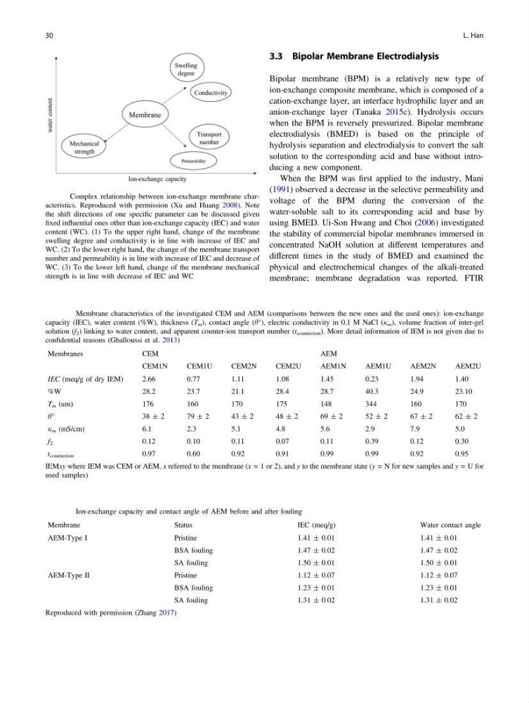
Fig. 1 Complex relationship between ion-exchange membrane characteristics. Reproduced with permission (Xu and Huang 2008). Note
the shift directions of one specific parameter can be discussed given
fixed influential ones other than ion-exchange capacity (IEC) and water
content (WC). (1) To the upper right hand, change of the membrane
swelling degree and conductivity is in line with increase of IEC and
WC. (2) To the lower right hand, the change of the membrane transport
number and permeability is in line with increase of IEC and decrease of
WC. (3) To the lower left hand, change of the membrane mechanical
strength is in line with decrease of IEC and WC
Table 2 Membrane characteristics of the investigated CEM and AEM (comparisons between the new ones and the used ones): ion-exchange
capacity (IEC), water content (%W), thickness (T m ), contact angle (h°), electric conductivity in 0.1 M NaCl (j m ), volume fraction of inter-gel
solution (f 2 ) linking to water content, and apparent counter-ion transport number (t counterion ). More detail information of IEM is not given due to
confidential reasons (Ghalloussi et al. 2013)
Membranes
CEM
AEM
CEM1N
CEM1U
CEM2N
CEM2U
AEM1N
AEM1U
AEM2N
AEM2U
IEC (meq/g of dry IEM)
2.66
0.77
1.11
1.08
1.45
0.23
1.94
1.40
%W
28.2
23.7
21.1
28.4
28.7
40.3
24.9
23.10
T m (um)
176
160
170
175
148
344
160
170
h°
3 8 ± 2
7 9± 2
4 3± 2
4 8± 2
6 9± 2
5 2± 2
6 7± 2
6 2± 2
j m (mS/cm)
6.1
2.3
5.1
4.8
5.6
2.9
7.9
5.0
f 2
0.12
0.10
0.11
0.07
0.11
0.39
0.12
0.30
t counterion
0.97
0.60
0.92
0.91
0.99
0.99
0.92
0.95
IEMxy where IEM was CEM or AEM, x referred to the membrane (x = 1 or 2), and y to the membrane state (y = N for new samples and y = U for
used samples)
Table 3 Ion-exchange capacity and contact angle of AEM before and after fouling
Membrane
Status
IEC (meq/g)
Water contact angle
AEM-Type I
Pristine
1.41 ± 0.01
1.41 ± 0.01
BSA fouling
1.47 ± 0.02
1.47 ± 0.02
SA fouling
1.50 ± 0.01
1.50 ± 0.01
AEM-Type II
Pristine
1.12 ± 0.07
1.12 ± 0.07
BSA fouling
1.23 ± 0.01
1.23 ± 0.01
SA fouling
1.31 ± 0.02
1.31 ± 0.02
Reproduced with permission (Zhang 2017)
30
L. Han
Bipolar membrane (BPM) is a relatively new type of
ion-exchange composite membrane, which is composed of a
cation-exchange layer, an interface hydrophilic layer and an
anion-exchange layer (Tanaka 2015c). Hydrolysis occurs
when the BPM is reversely pressurized. Bipolar membrane
electrodialysis (BMED) is based on the principle of
hydrolysis separation and electrodialysis to convert the salt
solution to the corresponding acid and base without introducing a new component.
When the BPM was first applied to the industry, Mani
(1991) observed a decrease in the selective permeability and
voltage of the BPM during the conversion of the
water-soluble salt to its corresponding acid and base by
using BMED. Ui-Son Hwang and Choi (2006) investigated
the stability of commercial bipolar membranes immersed in
concentrated NaOH solution at different temperatures and
different times in the study of BMED and examined the
physical and electrochemical changes of the alkali-treated
membrane; membrane degradation was reported. FTIR
Fig. 1 Complex relationship between ion-exchange membrane characteristics. Reproduced with permission (Xu and Huang 2008). Note
the shift directions of one specific parameter can be discussed given
fixed influential ones other than ion-exchange capacity (IEC) and water
content (WC). (1) To the upper right hand, change of the membrane
swelling degree and conductivity is in line with increase of IEC and
WC. (2) To the lower right hand, the change of the membrane transport
number and permeability is in line with increase of IEC and decrease of
WC. (3) To the lower left hand, change of the membrane mechanical
strength is in line with decrease of IEC and WC
Table 2 Membrane characteristics of the investigated CEM and AEM (comparisons between the new ones and the used ones): ion-exchange
capacity (IEC), water content (%W), thickness (T m ), contact angle (h°), electric conductivity in 0.1 M NaCl (j m ), volume fraction of inter-gel
solution (f 2 ) linking to water content, and apparent counter-ion transport number (t counterion ). More detail information of IEM is not given due to
confidential reasons (Ghalloussi et al. 2013)
Membranes
CEM
AEM
CEM1N
CEM1U
CEM2N
CEM2U
AEM1N
AEM1U
AEM2N
AEM2U
IEC (meq/g of dry IEM)
2.66
0.77
1.11
1.08
1.45
0.23
1.94
1.40
%W
28.2
23.7
21.1
28.4
28.7
40.3
24.9
23.10
T m (um)
176
160
170
175
148
344
160
170
h°
3 8 ± 2
7 9± 2
4 3± 2
4 8± 2
6 9± 2
5 2± 2
6 7± 2
6 2± 2
j m (mS/cm)
6.1
2.3
5.1
4.8
5.6
2.9
7.9
5.0
f 2
0.12
0.10
0.11
0.07
0.11
0.39
0.12
0.30
t counterion
0.97
0.60
0.92
0.91
0.99
0.99
0.92
0.95
IEMxy where IEM was CEM or AEM, x referred to the membrane (x = 1 or 2), and y to the membrane state (y = N for new samples and y = U for
used samples)
Table 3 Ion-exchange capacity and contact angle of AEM before and after fouling
Membrane
Status
IEC (meq/g)
Water contact angle
AEM-Type I
Pristine
1.41 ± 0.01
1.41 ± 0.01
BSA fouling
1.47 ± 0.02
1.47 ± 0.02
SA fouling
1.50 ± 0.01
1.50 ± 0.01
AEM-Type II
Pristine
1.12 ± 0.07
1.12 ± 0.07
BSA fouling
1.23 ± 0.01
1.23 ± 0.01
SA fouling
1.31 ± 0.02
1.31 ± 0.02
Reproduced with permission (Zhang 2017)
30
L. Han