

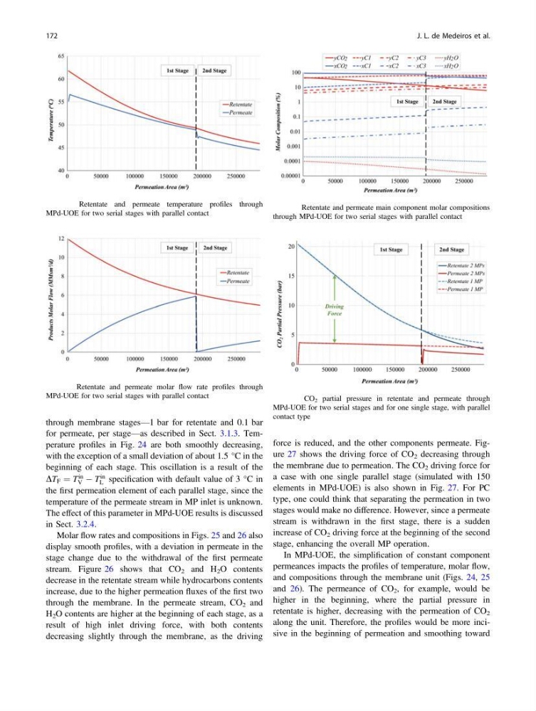
through membrane stages—1 bar for retentate and 0.1 bar
for permeate, per stage—as described in Sect. 3.1.3. Temperature profiles in Fig. 24 are both smoothly decreasing,
with the exception of a small deviation of about 1.5 °C in the
beginning of each stage. This oscillation is a result of the
DT F ¼ T
in
V À T
in
L specification with default value of 3 °C in
the first permeation element of each parallel stage, since the
temperature of the permeate stream in MP inlet is unknown.
The effect of this parameter in MPd-UOE results is discussed
in Sect. 3.2.4.
Molar flow rates and compositions in Figs. 25 and 26 also
display smooth profiles, with a deviation in permeate in the
stage change due to the withdrawal of the first permeate
stream. Figure 26 shows that CO 2 and H 2 O contents
decrease in the retentate stream while hydrocarbons contents
increase, due to the higher permeation fluxes of the first two
through the membrane. In the permeate stream, CO 2 and
H 2 O contents are higher at the beginning of each stage, as a
result of high inlet driving force, with both contents
decreasing slightly through the membrane, as the driving
force is reduced, and the other components permeate. Figure 27 shows the driving force of CO 2 decreasing through
the membrane due to permeation. The CO 2 driving force for
a case with one single parallel stage (simulated with 150
elements in MPd-UOE) is also shown in Fig. 27. For PC
type, one could think that separating the permeation in two
stages would make no difference. However, since a permeate
stream is withdrawn in the first stage, there is a sudden
increase of CO 2 driving force at the beginning of the second
stage, enhancing the overall MP operation.
In MPd-UOE, the simplification of constant component
permeances impacts the profiles of temperature, molar flow,
and compositions through the membrane unit (Figs. 24, 25
and 26). The permeance of CO 2 , for example, would be
higher in the beginning, where the partial pressure in
retentate is higher, decreasing with the permeation of CO 2
along the unit. Therefore, the profiles would be more incisive in the beginning of permeation and smoothing toward
Fig. 24 Retentate and permeate temperature profiles through
MPd-UOE for two serial stages with parallel contact
Fig. 25 Retentate and permeate molar flow rate profiles through
MPd-UOE for two serial stages with parallel contact
Fig. 26 Retentate and permeate main component molar compositions
through MPd-UOE for two serial stages with parallel contact
Fig. 27 CO 2 partial pressure in retentate and permeate through
MPd-UOE for two serial stages and for one single stage, with parallel
contact type
172
J. L. de Medeiros et al.
for permeate, per stage—as described in Sect. 3.1.3. Temperature profiles in Fig. 24 are both smoothly decreasing,
with the exception of a small deviation of about 1.5 °C in the
beginning of each stage. This oscillation is a result of the
DT F ¼ T
in
V À T
in
L specification with default value of 3 °C in
the first permeation element of each parallel stage, since the
temperature of the permeate stream in MP inlet is unknown.
The effect of this parameter in MPd-UOE results is discussed
in Sect. 3.2.4.
Molar flow rates and compositions in Figs. 25 and 26 also
display smooth profiles, with a deviation in permeate in the
stage change due to the withdrawal of the first permeate
stream. Figure 26 shows that CO 2 and H 2 O contents
decrease in the retentate stream while hydrocarbons contents
increase, due to the higher permeation fluxes of the first two
through the membrane. In the permeate stream, CO 2 and
H 2 O contents are higher at the beginning of each stage, as a
result of high inlet driving force, with both contents
decreasing slightly through the membrane, as the driving
force is reduced, and the other components permeate. Figure 27 shows the driving force of CO 2 decreasing through
the membrane due to permeation. The CO 2 driving force for
a case with one single parallel stage (simulated with 150
elements in MPd-UOE) is also shown in Fig. 27. For PC
type, one could think that separating the permeation in two
stages would make no difference. However, since a permeate
stream is withdrawn in the first stage, there is a sudden
increase of CO 2 driving force at the beginning of the second
stage, enhancing the overall MP operation.
In MPd-UOE, the simplification of constant component
permeances impacts the profiles of temperature, molar flow,
and compositions through the membrane unit (Figs. 24, 25
and 26). The permeance of CO 2 , for example, would be
higher in the beginning, where the partial pressure in
retentate is higher, decreasing with the permeation of CO 2
along the unit. Therefore, the profiles would be more incisive in the beginning of permeation and smoothing toward
Fig. 24 Retentate and permeate temperature profiles through
MPd-UOE for two serial stages with parallel contact
Fig. 25 Retentate and permeate molar flow rate profiles through
MPd-UOE for two serial stages with parallel contact
Fig. 26 Retentate and permeate main component molar compositions
through MPd-UOE for two serial stages with parallel contact
Fig. 27 CO 2 partial pressure in retentate and permeate through
MPd-UOE for two serial stages and for one single stage, with parallel
contact type
172
J. L. de Medeiros et al.