

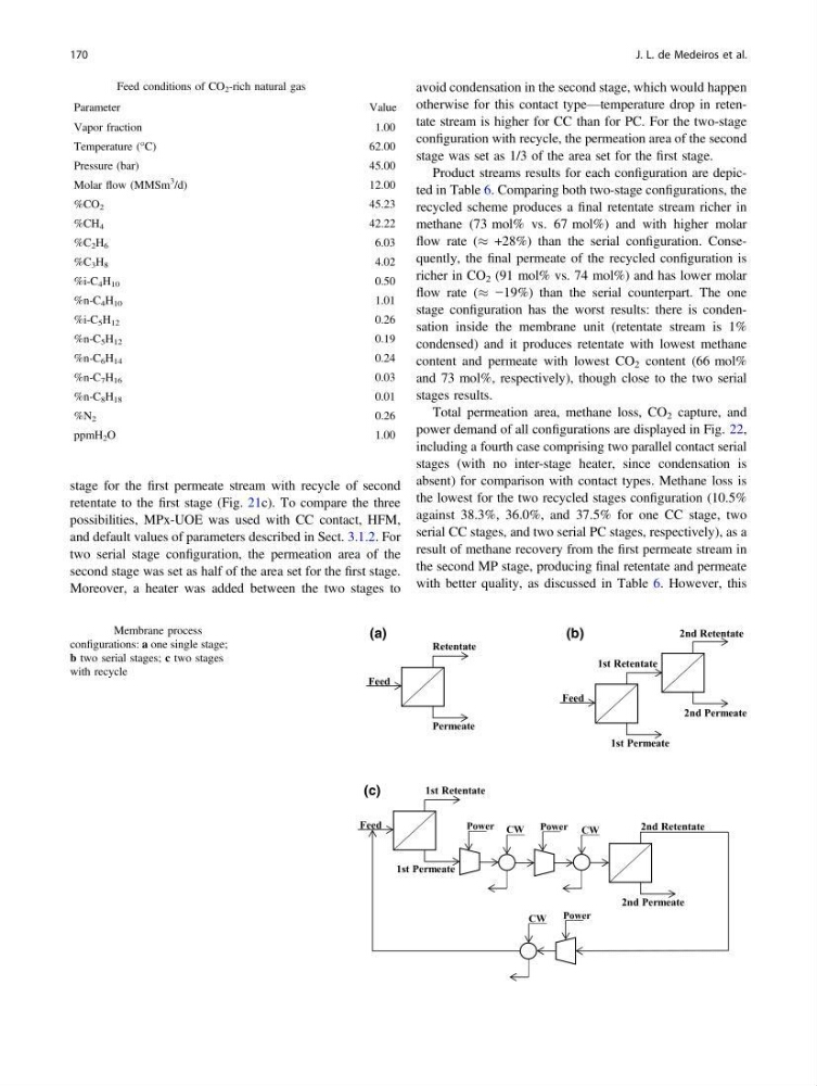
stage for the first permeate stream with recycle of second
retentate to the first stage (Fig. 21c). To compare the three
possibilities, MPx-UOE was used with CC contact, HFM,
and default values of parameters described in Sect. 3.1.2. For
two serial stage configuration, the permeation area of the
second stage was set as half of the area set for the first stage.
Moreover, a heater was added between the two stages to
avoid condensation in the second stage, which would happen
otherwise for this contact type—temperature drop in retentate stream is higher for CC than for PC. For the two-stage
configuration with recycle, the permeation area of the second
stage was set as 1/3 of the area set for the first stage.
Product streams results for each configuration are depicted in Table 6. Comparing both two-stage configurations, the
recycled scheme produces a final retentate stream richer in
methane (73 mol% vs. 67 mol%) and with higher molar
flow rate (% +28%) than the serial configuration. Consequently, the final permeate of the recycled configuration is
richer in CO 2 (91 mol% vs. 74 mol%) and has lower molar
flow rate (% −19%) than the serial counterpart. The one
stage configuration has the worst results: there is condensation inside the membrane unit (retentate stream is 1%
condensed) and it produces retentate with lowest methane
content and permeate with lowest CO 2 content (66 mol%
and 73 mol%, respectively), though close to the two serial
stages results.
Total permeation area, methane loss, CO 2 capture, and
power demand of all configurations are displayed in Fig. 22,
including a fourth case comprising two parallel contact serial
stages (with no inter-stage heater, since condensation is
absent) for comparison with contact types. Methane loss is
the lowest for the two recycled stages configuration (10.5%
against 38.3%, 36.0%, and 37.5% for one CC stage, two
serial CC stages, and two serial PC stages, respectively), as a
result of methane recovery from the first permeate stream in
the second MP stage, producing final retentate and permeate
with better quality, as discussed in Table 6. However, this
Table 5 Feed conditions of CO 2 -rich natural gas
Parameter
Value
Vapor fraction
1.00
Temperature (°C)
62.00
Pressure (bar)
45.00
Molar flow (MMSm
3
/d)
12.00
%CO 2
45.23
%CH 4
42.22
%C 2 H 6
6.03
%C 3 H 8
4.02
%i-C 4 H 10
0.50
%n-C 4 H 10
1.01
%i-C 5 H 12
0.26
%n-C 5 H 12
0.19
%n-C 6 H 14
0.24
%n-C 7 H 16
0.03
%n-C 8 H 18
0.01
%N 2
0.26
ppmH 2 O
1.00
Feed
Retentate
Permeate
Feed
Feed
1st Retentate
2nd Retentate
1st Permeate
2nd Permeate
1st Retentate
1st Permeate
2nd Permeate
2nd Retentate
CW
CW
CW
(a)
(b)
(c)
Power
Power
Power
Fig. 21 Membrane process
configurations: a one single stage;
b two serial stages; c two stages
with recycle
170
J. L. de Medeiros et al.
retentate to the first stage (Fig. 21c). To compare the three
possibilities, MPx-UOE was used with CC contact, HFM,
and default values of parameters described in Sect. 3.1.2. For
two serial stage configuration, the permeation area of the
second stage was set as half of the area set for the first stage.
Moreover, a heater was added between the two stages to
avoid condensation in the second stage, which would happen
otherwise for this contact type—temperature drop in retentate stream is higher for CC than for PC. For the two-stage
configuration with recycle, the permeation area of the second
stage was set as 1/3 of the area set for the first stage.
Product streams results for each configuration are depicted in Table 6. Comparing both two-stage configurations, the
recycled scheme produces a final retentate stream richer in
methane (73 mol% vs. 67 mol%) and with higher molar
flow rate (% +28%) than the serial configuration. Consequently, the final permeate of the recycled configuration is
richer in CO 2 (91 mol% vs. 74 mol%) and has lower molar
flow rate (% −19%) than the serial counterpart. The one
stage configuration has the worst results: there is condensation inside the membrane unit (retentate stream is 1%
condensed) and it produces retentate with lowest methane
content and permeate with lowest CO 2 content (66 mol%
and 73 mol%, respectively), though close to the two serial
stages results.
Total permeation area, methane loss, CO 2 capture, and
power demand of all configurations are displayed in Fig. 22,
including a fourth case comprising two parallel contact serial
stages (with no inter-stage heater, since condensation is
absent) for comparison with contact types. Methane loss is
the lowest for the two recycled stages configuration (10.5%
against 38.3%, 36.0%, and 37.5% for one CC stage, two
serial CC stages, and two serial PC stages, respectively), as a
result of methane recovery from the first permeate stream in
the second MP stage, producing final retentate and permeate
with better quality, as discussed in Table 6. However, this
Table 5 Feed conditions of CO 2 -rich natural gas
Parameter
Value
Vapor fraction
1.00
Temperature (°C)
62.00
Pressure (bar)
45.00
Molar flow (MMSm
3
/d)
12.00
%CO 2
45.23
%CH 4
42.22
%C 2 H 6
6.03
%C 3 H 8
4.02
%i-C 4 H 10
0.50
%n-C 4 H 10
1.01
%i-C 5 H 12
0.26
%n-C 5 H 12
0.19
%n-C 6 H 14
0.24
%n-C 7 H 16
0.03
%n-C 8 H 18
0.01
%N 2
0.26
ppmH 2 O
1.00
Feed
Retentate
Permeate
Feed
Feed
1st Retentate
2nd Retentate
1st Permeate
2nd Permeate
1st Retentate
1st Permeate
2nd Permeate
2nd Retentate
CW
CW
CW
(a)
(b)
(c)
Power
Power
Power
Fig. 21 Membrane process
configurations: a one single stage;
b two serial stages; c two stages
with recycle
170
J. L. de Medeiros et al.