

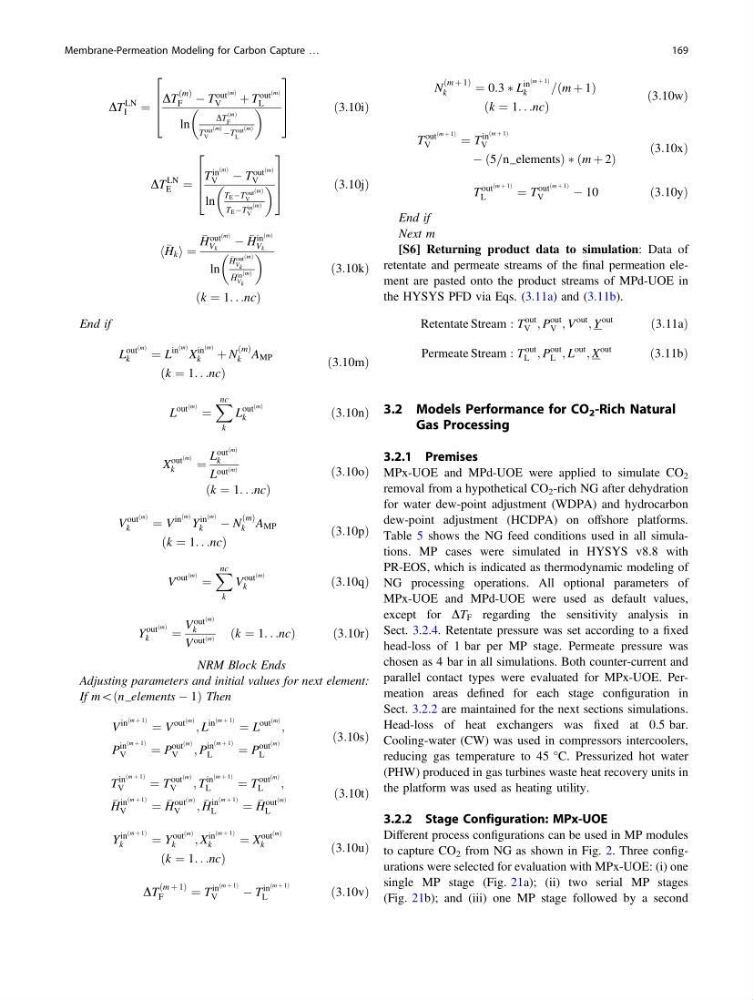
DT
LN
I
¼
DT
ðmÞ
F À T
out
ðmÞ
V
þ T
out
ðmÞ
L
ln
DT
ðmÞ
F
T out ðmÞ
V
ÀT out ðmÞ
L
2
6
6
4
3
7
7
5
ð3:10iÞ
DT
LN
E ¼
T
in
ðmÞ
V
À T
out
ðmÞ
V
ln
T E ÀT out ðmÞ
V
T E ÀT in ðmÞ
V
2
6
6
4
3
7
7
5
ð3:10jÞ
H k
h i ¼
H
out
ðmÞ
V k
À
H
in
ðmÞ
V k
ln
H out ðmÞ
V k
H in ðmÞ
V k
ðk ¼ 1. . .ncÞ
ð3:10kÞ
End if
L
out
ðmÞ
k
¼ L
in
ðmÞ X
in
ðmÞ
k
þ N
ðmÞ
k A MP
ðk ¼ 1. . .ncÞ
ð3:10mÞ
L
out
ðmÞ ¼
X nc
k
L
out
ðmÞ
k
ð3:10nÞ
X
out
ðmÞ
k
¼
L
out
ðmÞ
k
L out ðmÞ
ðk ¼ 1. . .ncÞ
ð3:10oÞ
V
out
ðmÞ
k
¼ V
in
ðmÞ Y
in
ðmÞ
k
À N
ðmÞ
k A MP
ðk ¼ 1. . .ncÞ
ð3:10pÞ
V
out
ðmÞ ¼
X nc
k
V
out
ðmÞ
k
ð3:10qÞ
Y
out
ðmÞ
k
¼
V
out
ðmÞ
k
V out ðmÞ ðk ¼ 1. . .ncÞ
ð3:10rÞ
NRM Block Ends
Adjusting parameters and initial values for next element:
If m\ðn elements À 1Þ Then
V
in
ðm þ 1Þ ¼ V
out
ðmÞ ; L
in
ðm þ 1Þ ¼ L
out
ðmÞ ;
P
in
ðm þ 1Þ
V
¼ P
out
ðmÞ
V
; P
in
ðm þ 1Þ
L
¼ P
out
ðmÞ
L
ð3:10sÞ
T
in
ðm þ 1Þ
V
¼ T
out
ðmÞ
V
; T
in
ðm þ 1Þ
L
¼ T
out
ðmÞ
L
;
H
in
ðm þ 1Þ
V
¼
H
out
ðmÞ
V
;
H
in
ðm þ 1Þ
L
¼
H
out
ðmÞ
L
ð3:10tÞ
Y
in
ðm þ 1Þ
k
¼ Y
out
ðmÞ
k
; X
in
ðm þ 1Þ
k
¼ X
out
ðmÞ
k
ðk ¼ 1. . .ncÞ
ð3:10uÞ
DT
ðm þ 1Þ
F
¼ T
in
ðm þ 1Þ
V
À T
in
ðm þ 1Þ
L
ð3:10vÞ
N
ðm þ 1Þ
k
¼ 0:3 Ã L
in
ðm þ 1Þ
k
=ðm þ 1Þ
ðk ¼ 1. . .ncÞ
ð3:10wÞ
T
out
ðm þ 1Þ
V
¼ T
in
ðm þ 1Þ
V
À ð5=n elementsÞ Ã ðm þ 2Þ
ð3:10xÞ
T
out
ðm þ 1Þ
L
¼ T
out
ðm þ 1Þ
V
À 10
ð3:10yÞ
End if
Next m
[S6] Returning product data to simulation: Data of
retentate and permeate streams of the final permeation element are pasted onto the product streams of MPd-UOE in
the HYSYS PFD via Eqs. (3.11a) and (3.11b).
Retentate Stream : T
out
V ; P
out
V ; V
out
; Y
out
ð3:11aÞ
Permeate Stream : T
out
L ; P
out
L ; L
out
; X
out
ð3:11bÞ
3.2 Models Performance for CO 2 -Rich Natural
Gas Processing
3.2.1 Premises
MPx-UOE and MPd-UOE were applied to simulate CO 2
removal from a hypothetical CO 2 -rich NG after dehydration
for water dew-point adjustment (WDPA) and hydrocarbon
dew-point adjustment (HCDPA) on offshore platforms.
Table 5 shows the NG feed conditions used in all simulations. MP cases were simulated in HYSYS v8.8 with
PR-EOS, which is indicated as thermodynamic modeling of
NG processing operations. All optional parameters of
MPx-UOE and MPd-UOE were used as default values,
except for DT F regarding the sensitivity analysis in
Sect. 3.2.4. Retentate pressure was set according to a fixed
head-loss of 1 bar per MP stage. Permeate pressure was
chosen as 4 bar in all simulations. Both counter-current and
parallel contact types were evaluated for MPx-UOE. Permeation areas defined for each stage configuration in
Sect. 3.2.2 are maintained for the next sections simulations.
Head-loss of heat exchangers was fixed at 0.5 bar.
Cooling-water (CW) was used in compressors intercoolers,
reducing gas temperature to 45 °C. Pressurized hot water
(PHW) produced in gas turbines waste heat recovery units in
the platform was used as heating utility.
3.2.2 Stage Configuration: MPx-UOE
Different process configurations can be used in MP modules
to capture CO 2 from NG as shown in Fig. 2. Three configurations were selected for evaluation with MPx-UOE: (i) one
single MP stage (Fig. 21a); (ii) two serial MP stages
(Fig. 21b); and (iii) one MP stage followed by a second
Membrane-Permeation Modeling for Carbon Capture …
169
LN
I
¼
DT
ðmÞ
F À T
out
ðmÞ
V
þ T
out
ðmÞ
L
ln
DT
ðmÞ
F
T out ðmÞ
V
ÀT out ðmÞ
L
2
6
6
4
3
7
7
5
ð3:10iÞ
DT
LN
E ¼
T
in
ðmÞ
V
À T
out
ðmÞ
V
ln
T E ÀT out ðmÞ
V
T E ÀT in ðmÞ
V
2
6
6
4
3
7
7
5
ð3:10jÞ
H k
h i ¼
H
out
ðmÞ
V k
À
H
in
ðmÞ
V k
ln
H out ðmÞ
V k
H in ðmÞ
V k
ðk ¼ 1. . .ncÞ
ð3:10kÞ
End if
L
out
ðmÞ
k
¼ L
in
ðmÞ X
in
ðmÞ
k
þ N
ðmÞ
k A MP
ðk ¼ 1. . .ncÞ
ð3:10mÞ
L
out
ðmÞ ¼
X nc
k
L
out
ðmÞ
k
ð3:10nÞ
X
out
ðmÞ
k
¼
L
out
ðmÞ
k
L out ðmÞ
ðk ¼ 1. . .ncÞ
ð3:10oÞ
V
out
ðmÞ
k
¼ V
in
ðmÞ Y
in
ðmÞ
k
À N
ðmÞ
k A MP
ðk ¼ 1. . .ncÞ
ð3:10pÞ
V
out
ðmÞ ¼
X nc
k
V
out
ðmÞ
k
ð3:10qÞ
Y
out
ðmÞ
k
¼
V
out
ðmÞ
k
V out ðmÞ ðk ¼ 1. . .ncÞ
ð3:10rÞ
NRM Block Ends
Adjusting parameters and initial values for next element:
If m\ðn elements À 1Þ Then
V
in
ðm þ 1Þ ¼ V
out
ðmÞ ; L
in
ðm þ 1Þ ¼ L
out
ðmÞ ;
P
in
ðm þ 1Þ
V
¼ P
out
ðmÞ
V
; P
in
ðm þ 1Þ
L
¼ P
out
ðmÞ
L
ð3:10sÞ
T
in
ðm þ 1Þ
V
¼ T
out
ðmÞ
V
; T
in
ðm þ 1Þ
L
¼ T
out
ðmÞ
L
;
H
in
ðm þ 1Þ
V
¼
H
out
ðmÞ
V
;
H
in
ðm þ 1Þ
L
¼
H
out
ðmÞ
L
ð3:10tÞ
Y
in
ðm þ 1Þ
k
¼ Y
out
ðmÞ
k
; X
in
ðm þ 1Þ
k
¼ X
out
ðmÞ
k
ðk ¼ 1. . .ncÞ
ð3:10uÞ
DT
ðm þ 1Þ
F
¼ T
in
ðm þ 1Þ
V
À T
in
ðm þ 1Þ
L
ð3:10vÞ
N
ðm þ 1Þ
k
¼ 0:3 Ã L
in
ðm þ 1Þ
k
=ðm þ 1Þ
ðk ¼ 1. . .ncÞ
ð3:10wÞ
T
out
ðm þ 1Þ
V
¼ T
in
ðm þ 1Þ
V
À ð5=n elementsÞ Ã ðm þ 2Þ
ð3:10xÞ
T
out
ðm þ 1Þ
L
¼ T
out
ðm þ 1Þ
V
À 10
ð3:10yÞ
End if
Next m
[S6] Returning product data to simulation: Data of
retentate and permeate streams of the final permeation element are pasted onto the product streams of MPd-UOE in
the HYSYS PFD via Eqs. (3.11a) and (3.11b).
Retentate Stream : T
out
V ; P
out
V ; V
out
; Y
out
ð3:11aÞ
Permeate Stream : T
out
L ; P
out
L ; L
out
; X
out
ð3:11bÞ
3.2 Models Performance for CO 2 -Rich Natural
Gas Processing
3.2.1 Premises
MPx-UOE and MPd-UOE were applied to simulate CO 2
removal from a hypothetical CO 2 -rich NG after dehydration
for water dew-point adjustment (WDPA) and hydrocarbon
dew-point adjustment (HCDPA) on offshore platforms.
Table 5 shows the NG feed conditions used in all simulations. MP cases were simulated in HYSYS v8.8 with
PR-EOS, which is indicated as thermodynamic modeling of
NG processing operations. All optional parameters of
MPx-UOE and MPd-UOE were used as default values,
except for DT F regarding the sensitivity analysis in
Sect. 3.2.4. Retentate pressure was set according to a fixed
head-loss of 1 bar per MP stage. Permeate pressure was
chosen as 4 bar in all simulations. Both counter-current and
parallel contact types were evaluated for MPx-UOE. Permeation areas defined for each stage configuration in
Sect. 3.2.2 are maintained for the next sections simulations.
Head-loss of heat exchangers was fixed at 0.5 bar.
Cooling-water (CW) was used in compressors intercoolers,
reducing gas temperature to 45 °C. Pressurized hot water
(PHW) produced in gas turbines waste heat recovery units in
the platform was used as heating utility.
3.2.2 Stage Configuration: MPx-UOE
Different process configurations can be used in MP modules
to capture CO 2 from NG as shown in Fig. 2. Three configurations were selected for evaluation with MPx-UOE: (i) one
single MP stage (Fig. 21a); (ii) two serial MP stages
(Fig. 21b); and (iii) one MP stage followed by a second
Membrane-Permeation Modeling for Carbon Capture …
169