

better mol% CO 2 than the previous case in Sect. 2.3. On the
other hand, if less HFM elements are to be used for same gas
feed—i.e., each HFM 10 m  0.2 m element has a greater
gas flow rate to re-erect selectivity—it also should be
expected a greater head-loss through the HFM elements in
the first MP stage. In other words, the retentate from the first
MP stage are expected to attain a lower outlet pressure (P
out
V )
relatively to the same result in Sect. 2.3. Besides, thanks to
the greater expansion to P L
out = 7 bar, the temperature fall
through the first MP stage will also be greater due to a
deeper Joule–Thomson effect. Process specifications
(Sect. 2.1.4) are the same of Sect. 2.3, except that lower
P L
out and less HFM modules are used: N M = 20 (per battery); P L
out = 7 bar; (iii) G60 feed (F
Feed , Y
Feed , P
Feed , T
Feed )
in Table 3; (iv) DP
HEX = 0.5 bar, T
Heater = 45 °C,
T
Cooler = 30 °C; (v) compressor adiabatic efficiency η% =
75%; (vi) two-phase mixer-cooler M2F at T
M2F = 5 °C.
Thus, the flowsheet FGc20p7 proposes producing 20 mol
% CO 2 FG via two smaller serial MP batteries (Fig. 2) with
N M = 20 HFM 10 m  0.2 m elements each (Table 2) both
with permeate outlet at P L
out = 7 bar. Again, the second MP
battery (MP#2) is used only if the first MP battery (MP#1)
does not accomplish targets. Flowsheet FGc20p7 is shown
in Fig. 16 using the rules in Fig. 4 for stream names. Since
this deeper MP operation generates a greater cooling than the
previous case in Sect. 2.3, FGc20p7 firstly apply the same
hydrocarbon dew-point adjustment (HCDPA) of G60 by
cooling it to T = 5 °C in the same two-phase mixer-cooler
(M2F) followed by a two-phase separator (S2F) for liquid
separation. The same small condensation of NGL occurs
reducing the split vapor flow rate to 1.4581 MMNm
3 /d. As a
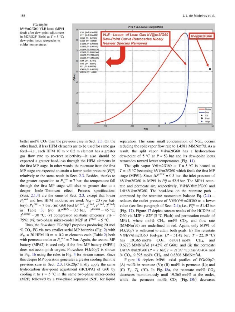
result, the split vapor V@m2fG60 has a hydrocarbon
dew-point of 5 °C at P = 53 bar and its dew-point locus
retrocedes toward lower temperatures (Fig. 11).
The split vapor V@m2fG60 at T = 5 °C is heated to
T = 45 °C becoming hV@m2fG60 which feeds the first MP
stage (MP#1). Since DP
HEX = 0.5 bar, the inlet pressure of
hV@m2fG60 in MP#1 is P
in
V ¼ 52:5 bar. The MP#1 retentate and permeate are, respectively, V@hV@m2fG60 and
L@hV@m2fG60. The head-loss on the retentate path—
computed by the retentate momentum balance Eq. (2.4)—
reduces the outlet pressure of V@hV@m2fG60 to a lower
value (see first paragraph of Sect. 2.4); i.e., P
out
V ¼ 51:42 bar
(Fig. 17). Figure 17 depicts stream results of the HCDPA of
G60 via M2F + S2F (5 °C Flash) and permeation results of
MP#1, where mol% CH 4 , mol% CO 2 , and flow rate
(MMNm
3 /d) are underlined in red. Again, only MP#1 of
FGc20p7 is sufficient to attain both goals: (i) The retentate
V@hV@m2fG60 fuel-gas (P = 51.42 bar, T = 22.19 °C)
has 19.365 mol% CO 2 , 68.081 mol% CH 4 , and
0.6273 MMNm
3 /d (%42% of G60); and (ii) the permeate
L@hV@m2fG60 (P = 7 bar, T = 21.97 °C) has 90.404 mol
% CO 2 , 9.395 mol% CH 4 , and 0.8308 MMNm
3 /d.
Figure 18 depicts MP#1 axial profiles of FGc20p7:
(A) mol% in retentate (V); (B) mol% in permeate (L); and
(C) T V , T L (°C). In Fig. 18a, the retentate mol% CO 2
decreases monotonously until 19.365 mol% at the outlet,
while the permeate mol% CO 2 (Fig. 18b) decreases
VLE – Locus of Lean Gas hV@m2fG60
Dew-Point Curve Retrocedes Nicely
Heavier Species Removed
hV@m2fG60
Fig. 11 FGc40p20:
hV@m2fG60 VLE locus (MP#1
feed) after dew-point adjustment
in M2F/S2F (flash) at T = 5 °C;
dew-point locus retrocedes to
colder temperatures
156
J. L. de Medeiros et al.
other hand, if less HFM elements are to be used for same gas
feed—i.e., each HFM 10 m  0.2 m element has a greater
gas flow rate to re-erect selectivity—it also should be
expected a greater head-loss through the HFM elements in
the first MP stage. In other words, the retentate from the first
MP stage are expected to attain a lower outlet pressure (P
out
V )
relatively to the same result in Sect. 2.3. Besides, thanks to
the greater expansion to P L
out = 7 bar, the temperature fall
through the first MP stage will also be greater due to a
deeper Joule–Thomson effect. Process specifications
(Sect. 2.1.4) are the same of Sect. 2.3, except that lower
P L
out and less HFM modules are used: N M = 20 (per battery); P L
out = 7 bar; (iii) G60 feed (F
Feed , Y
Feed , P
Feed , T
Feed )
in Table 3; (iv) DP
HEX = 0.5 bar, T
Heater = 45 °C,
T
Cooler = 30 °C; (v) compressor adiabatic efficiency η% =
75%; (vi) two-phase mixer-cooler M2F at T
M2F = 5 °C.
Thus, the flowsheet FGc20p7 proposes producing 20 mol
% CO 2 FG via two smaller serial MP batteries (Fig. 2) with
N M = 20 HFM 10 m  0.2 m elements each (Table 2) both
with permeate outlet at P L
out = 7 bar. Again, the second MP
battery (MP#2) is used only if the first MP battery (MP#1)
does not accomplish targets. Flowsheet FGc20p7 is shown
in Fig. 16 using the rules in Fig. 4 for stream names. Since
this deeper MP operation generates a greater cooling than the
previous case in Sect. 2.3, FGc20p7 firstly apply the same
hydrocarbon dew-point adjustment (HCDPA) of G60 by
cooling it to T = 5 °C in the same two-phase mixer-cooler
(M2F) followed by a two-phase separator (S2F) for liquid
separation. The same small condensation of NGL occurs
reducing the split vapor flow rate to 1.4581 MMNm
3 /d. As a
result, the split vapor V@m2fG60 has a hydrocarbon
dew-point of 5 °C at P = 53 bar and its dew-point locus
retrocedes toward lower temperatures (Fig. 11).
The split vapor V@m2fG60 at T = 5 °C is heated to
T = 45 °C becoming hV@m2fG60 which feeds the first MP
stage (MP#1). Since DP
HEX = 0.5 bar, the inlet pressure of
hV@m2fG60 in MP#1 is P
in
V ¼ 52:5 bar. The MP#1 retentate and permeate are, respectively, V@hV@m2fG60 and
L@hV@m2fG60. The head-loss on the retentate path—
computed by the retentate momentum balance Eq. (2.4)—
reduces the outlet pressure of V@hV@m2fG60 to a lower
value (see first paragraph of Sect. 2.4); i.e., P
out
V ¼ 51:42 bar
(Fig. 17). Figure 17 depicts stream results of the HCDPA of
G60 via M2F + S2F (5 °C Flash) and permeation results of
MP#1, where mol% CH 4 , mol% CO 2 , and flow rate
(MMNm
3 /d) are underlined in red. Again, only MP#1 of
FGc20p7 is sufficient to attain both goals: (i) The retentate
V@hV@m2fG60 fuel-gas (P = 51.42 bar, T = 22.19 °C)
has 19.365 mol% CO 2 , 68.081 mol% CH 4 , and
0.6273 MMNm
3 /d (%42% of G60); and (ii) the permeate
L@hV@m2fG60 (P = 7 bar, T = 21.97 °C) has 90.404 mol
% CO 2 , 9.395 mol% CH 4 , and 0.8308 MMNm
3 /d.
Figure 18 depicts MP#1 axial profiles of FGc20p7:
(A) mol% in retentate (V); (B) mol% in permeate (L); and
(C) T V , T L (°C). In Fig. 18a, the retentate mol% CO 2
decreases monotonously until 19.365 mol% at the outlet,
while the permeate mol% CO 2 (Fig. 18b) decreases
VLE – Locus of Lean Gas hV@m2fG60
Dew-Point Curve Retrocedes Nicely
Heavier Species Removed
hV@m2fG60
Fig. 11 FGc40p20:
hV@m2fG60 VLE locus (MP#1
feed) after dew-point adjustment
in M2F/S2F (flash) at T = 5 °C;
dew-point locus retrocedes to
colder temperatures
156
J. L. de Medeiros et al.