

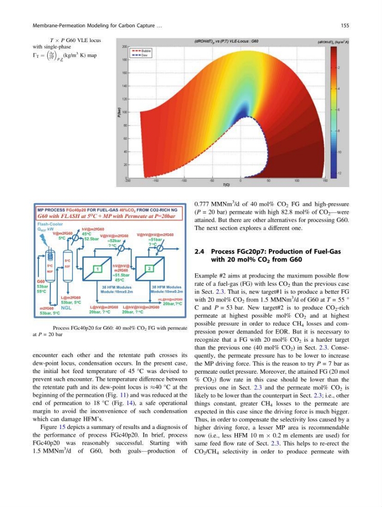
encounter each other and the retentate path crosses its
dew-point locus, condensation occurs. In the present case,
the initial hot feed temperature of 45 °C was devised to
prevent such encounter. The temperature difference between
the retentate path and its dew-point locus is %40 °C at the
beginning of the permeation (Fig. 11) and was reduced at the
end of permeation to 18 °C (Fig. 14), a safe operational
margin to avoid the inconvenience of such condensation
which can damage HFM’s.
Figure 15 depicts a summary of results and a diagnosis of
the performance of process FGc40p20. In brief, process
FGc40p20 was reasonably successful. Starting with
1.5 MMNm
3 /d of G60, both goals—production of
0.777 MMNm
3 /d of 40 mol% CO 2 FG and high-pressure
(P = 20 bar) permeate with high 82.8 mol% of CO 2 —were
attained. But there are other alternatives for processing G60.
The next section explores a different one.
2.4 Process FGc20p7: Production of Fuel-Gas
with 20 mol% CO 2 from G60
Example #2 aims at producing the maximum possible flow
rate of a fuel-gas (FG) with less CO 2 than the previous case
in Sect. 2.3. That is, new target#1 is to produce a better FG
with 20 mol% CO 2 from 1.5 MMNm
3 /d of G60 at T = 55 °
C and P = 53 bar. New target#2 is to produce CO 2 -rich
permeate at highest possible mol% CO 2 and at highest
possible pressure in order to reduce CH 4 losses and compression power demanded for EOR. But it is necessary to
recognize that a FG with 20 mol% CO 2 is a harder target
than the previous one (40 mol% CO 2 ) in Sect. 2.3. Consequently, the permeate pressure has to be lower to increase
the MP driving force. This is the reason to try P = 7 bar as
permeate outlet pressure. Moreover, the attained FG (20 mol
% CO 2 ) flow rate in this case should be lower than the
previous one in Sect. 2.3 and the permeate mol% CO 2 is
likely to be lower than the counterpart in Sect. 2.3; i.e., other
things constant, greater CH 4 losses to the permeate are
expected in this case since the driving force is much bigger.
Thus, in order to compensate the selectivity loss caused by a
higher driving force, a lesser MP area is recommendable
now (i.e., less HFM 10 m  0.2 m elements are used) for
same feed flow rate of Sect. 2.3. This helps to re-erect the
CO 2 /CH 4 selectivity in order to produce permeate with
Fig. 9 T Â P G60 VLE locus
with single-phase
C T ¼
@q
@T
P;Z
(kg/m
3 K) map
1
2
L@hV@m2fG60
20bar, ? o C
L@hV@hV@m2fG60
20bar, ? o C
mL@hV@m2fG60
20bar,? o C
G60
53bar
55 o C
V@hV@m2fG60
≈52bar
? o C
hV@hV@
m2fG60
≈51.5bar
45 o C
V@hV@hV@m2fG60
≈51bar
? o C
38 HFM Modules
Module:10mx0.2m
38 HFM Modules
Module:10mx0.2m
m2fG60
53bar, 5 o C
5 o C
S2F
5 o C
M2F
Flash-Cooler
Q M2F kW
L@m2fG60
53bar, 5 o C
NGL
V@m2fG60
5 o C
hV@m2fG60
45 o C
52.5bar
MP PROCESS FGc40p20 FOR FUEL-GAS 40%CO 2 FROM CO2-RICH NG
G60 with FLASH at 5 O C + MP with Permeate at P=20bar
Fig. 10 Process FGc40p20 for G60: 40 mol% CO 2 FG with permeate
at P = 20 bar
Membrane-Permeation Modeling for Carbon Capture …
155
dew-point locus, condensation occurs. In the present case,
the initial hot feed temperature of 45 °C was devised to
prevent such encounter. The temperature difference between
the retentate path and its dew-point locus is %40 °C at the
beginning of the permeation (Fig. 11) and was reduced at the
end of permeation to 18 °C (Fig. 14), a safe operational
margin to avoid the inconvenience of such condensation
which can damage HFM’s.
Figure 15 depicts a summary of results and a diagnosis of
the performance of process FGc40p20. In brief, process
FGc40p20 was reasonably successful. Starting with
1.5 MMNm
3 /d of G60, both goals—production of
0.777 MMNm
3 /d of 40 mol% CO 2 FG and high-pressure
(P = 20 bar) permeate with high 82.8 mol% of CO 2 —were
attained. But there are other alternatives for processing G60.
The next section explores a different one.
2.4 Process FGc20p7: Production of Fuel-Gas
with 20 mol% CO 2 from G60
Example #2 aims at producing the maximum possible flow
rate of a fuel-gas (FG) with less CO 2 than the previous case
in Sect. 2.3. That is, new target#1 is to produce a better FG
with 20 mol% CO 2 from 1.5 MMNm
3 /d of G60 at T = 55 °
C and P = 53 bar. New target#2 is to produce CO 2 -rich
permeate at highest possible mol% CO 2 and at highest
possible pressure in order to reduce CH 4 losses and compression power demanded for EOR. But it is necessary to
recognize that a FG with 20 mol% CO 2 is a harder target
than the previous one (40 mol% CO 2 ) in Sect. 2.3. Consequently, the permeate pressure has to be lower to increase
the MP driving force. This is the reason to try P = 7 bar as
permeate outlet pressure. Moreover, the attained FG (20 mol
% CO 2 ) flow rate in this case should be lower than the
previous one in Sect. 2.3 and the permeate mol% CO 2 is
likely to be lower than the counterpart in Sect. 2.3; i.e., other
things constant, greater CH 4 losses to the permeate are
expected in this case since the driving force is much bigger.
Thus, in order to compensate the selectivity loss caused by a
higher driving force, a lesser MP area is recommendable
now (i.e., less HFM 10 m  0.2 m elements are used) for
same feed flow rate of Sect. 2.3. This helps to re-erect the
CO 2 /CH 4 selectivity in order to produce permeate with
Fig. 9 T Â P G60 VLE locus
with single-phase
C T ¼
@q
@T
P;Z
(kg/m
3 K) map
1
2
L@hV@m2fG60
20bar, ? o C
L@hV@hV@m2fG60
20bar, ? o C
mL@hV@m2fG60
20bar,? o C
G60
53bar
55 o C
V@hV@m2fG60
≈52bar
? o C
hV@hV@
m2fG60
≈51.5bar
45 o C
V@hV@hV@m2fG60
≈51bar
? o C
38 HFM Modules
Module:10mx0.2m
38 HFM Modules
Module:10mx0.2m
m2fG60
53bar, 5 o C
5 o C
S2F
5 o C
M2F
Flash-Cooler
Q M2F kW
L@m2fG60
53bar, 5 o C
NGL
V@m2fG60
5 o C
hV@m2fG60
45 o C
52.5bar
MP PROCESS FGc40p20 FOR FUEL-GAS 40%CO 2 FROM CO2-RICH NG
G60 with FLASH at 5 O C + MP with Permeate at P=20bar
Fig. 10 Process FGc40p20 for G60: 40 mol% CO 2 FG with permeate
at P = 20 bar
Membrane-Permeation Modeling for Carbon Capture …
155