

Airborne Nanoparticles: Control and Detection,
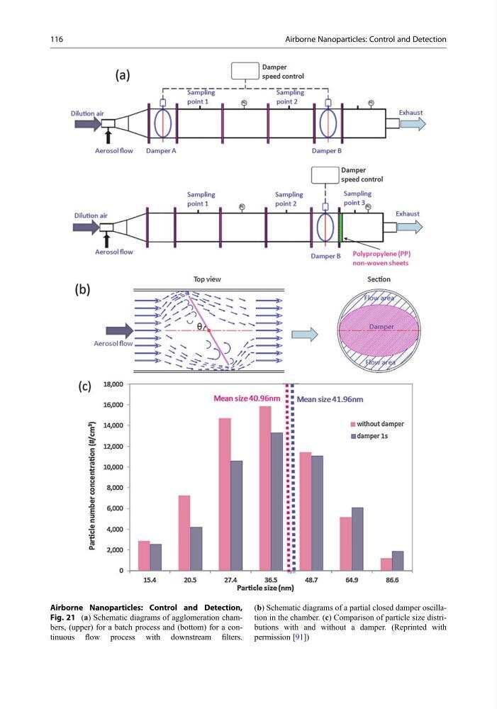
Fig. 21 (a) Schematic diagrams of agglomeration chambers, (upper) for a batch process and (bottom) for a continuous flow process with downstream filters.
(b) Schematic diagrams of a partial closed damper oscillation in the chamber. (c) Comparison of particle size distributions with and without a damper. (Reprinted with
permission [91])
116
Airborne Nanoparticles: Control and Detection
Fig. 21 (a) Schematic diagrams of agglomeration chambers, (upper) for a batch process and (bottom) for a continuous flow process with downstream filters.
(b) Schematic diagrams of a partial closed damper oscillation in the chamber. (c) Comparison of particle size distributions with and without a damper. (Reprinted with
permission [91])
116
Airborne Nanoparticles: Control and Detection