

RF frequencies bands: L: 12 GHz, S: 2-4 GHz, C: 48 GHz, X: 8-12 GHz.
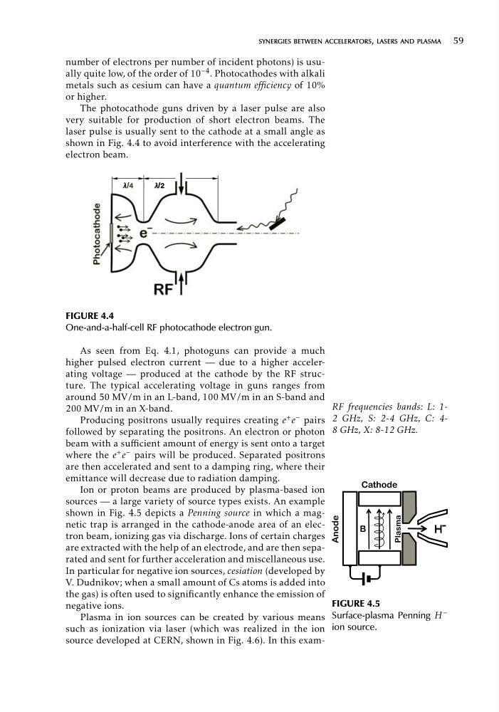
FIGURE 4.5
Surface-plasma Penning H −
ion source.
synergies between accelerators, lasers and plasma 59
number of electrons per number of incident photons) is usually quite low, of the order of 10 −4 . Photocathodes with alkali
metals such as cesium can have a quantum efficiency of 10%
or higher.
The photocathode guns driven by a laser pulse are also
very suitable for production of short electron beams. The
laser pulse is usually sent to the cathode at a small angle as
shown in Fig. 4.4 to avoid interference with the accelerating
electron beam.
FIGURE 4.4
One-and-a-half-cell RF photocathode electron gun.
As seen from Eq. 4.1, photoguns can provide a much
higher pulsed electron current — due to a higher accelerating voltage — produced at the cathode by the RF structure. The typical accelerating voltage in guns ranges from
around 50 MV/m in an L-band, 100 MV/m in an S-band and
200 MV/m in an X-band.
Producing positrons usually requires creating e + e − pairs
followed by separating the positrons. An electron or photon
beam with a sufficient amount of energy is sent onto a target
+
where the e e − pairs will be produced. Separated positrons
are then accelerated and sent to a damping ring, where their
emittance will decrease due to radiation damping.
Ion or proton beams are produced by plasma-based ion
sources — a large variety of source types exists. An example
shown in Fig. 4.5 depicts a Penning source in which a magnetic trap is arranged in the cathode-anode area of an electron beam, ionizing gas via discharge. Ions of certain charges
are extracted with the help of an electrode, and are then separated and sent for further acceleration and miscellaneous use.
In particular for negative ion sources, cesiation (developed by
V. Dudnikov; when a small amount of Cs atoms is added into
the gas) is often used to significantly enhance the emission of
negative ions.
Plasma in ion sources can be created by various means
such as ionization via laser (which was realized in the ion
source developed at CERN, shown in Fig. 4.6). In this exam
FIGURE 4.5
Surface-plasma Penning H −
ion source.
synergies between accelerators, lasers and plasma 59
number of electrons per number of incident photons) is usually quite low, of the order of 10 −4 . Photocathodes with alkali
metals such as cesium can have a quantum efficiency of 10%
or higher.
The photocathode guns driven by a laser pulse are also
very suitable for production of short electron beams. The
laser pulse is usually sent to the cathode at a small angle as
shown in Fig. 4.4 to avoid interference with the accelerating
electron beam.
FIGURE 4.4
One-and-a-half-cell RF photocathode electron gun.
As seen from Eq. 4.1, photoguns can provide a much
higher pulsed electron current — due to a higher accelerating voltage — produced at the cathode by the RF structure. The typical accelerating voltage in guns ranges from
around 50 MV/m in an L-band, 100 MV/m in an S-band and
200 MV/m in an X-band.
Producing positrons usually requires creating e + e − pairs
followed by separating the positrons. An electron or photon
beam with a sufficient amount of energy is sent onto a target
+
where the e e − pairs will be produced. Separated positrons
are then accelerated and sent to a damping ring, where their
emittance will decrease due to radiation damping.
Ion or proton beams are produced by plasma-based ion
sources — a large variety of source types exists. An example
shown in Fig. 4.5 depicts a Penning source in which a magnetic trap is arranged in the cathode-anode area of an electron beam, ionizing gas via discharge. Ions of certain charges
are extracted with the help of an electrode, and are then separated and sent for further acceleration and miscellaneous use.
In particular for negative ion sources, cesiation (developed by
V. Dudnikov; when a small amount of Cs atoms is added into
the gas) is often used to significantly enhance the emission of
negative ions.
Plasma in ion sources can be created by various means
such as ionization via laser (which was realized in the ion
source developed at CERN, shown in Fig. 4.6). In this exam