

220 unifying physics of accelerators, lasers and plasma
A typical layout of a detector and beamlines is shown in
Fig. 10.45. One can see here that an anti-solenoid is inserted
into the beamline. This anti-solenoid is needed to cancel the
beam coupling effects that the main solenoid produces on the
beam.
The problem with the anti-solenoid is that a huge force
will be exerted on it because of the main solenoid. A solution
implemented 18 in IR design is to use a dual anti-solenoid,
where the outer coil with current I 2 = −I 1 (R 1 /R 2 ) 2 cancels
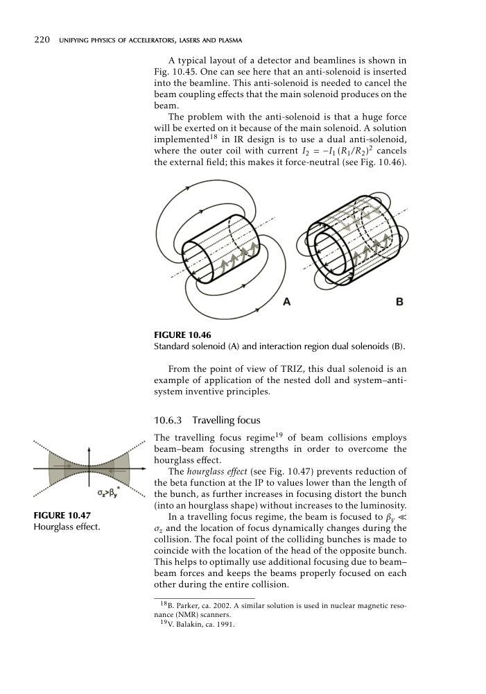
the external field; this makes it force-neutral (see Fig. 10.46).
FIGURE 10.46
FIGURE 10.47
Hourglass effect.
Standard solenoid (A) and interaction region dual solenoids (B).
From the point of view of TRIZ, this dual solenoid is an
example of application of the nested doll and system–antisystem inventive principles.
10.6.3 Travelling focus
The travelling focus regime 19 of beam collisions employs
beam–beam focusing strengths in order to overcome the
hourglass effect.
The hourglass effect (see Fig. 10.47) prevents reduction of
the beta function at the IP to values lower than the length of
the bunch, as further increases in focusing distort the bunch
(into an hourglass shape) without increases to the luminosity.
In a travelling focus regime, the beam is focused to β y «
σ z and the location of focus dynamically changes during the
collision. The focal point of the colliding bunches is made to
coincide with the location of the head of the opposite bunch.
This helps to optimally use additional focusing due to beam–
beam forces and keeps the beams properly focused on each
other during the entire collision.
18 B. Parker, ca. 2002. A similar solution is used in nuclear magnetic resonance (NMR) scanners.
19 V. Balakin, ca. 1991.
A typical layout of a detector and beamlines is shown in
Fig. 10.45. One can see here that an anti-solenoid is inserted
into the beamline. This anti-solenoid is needed to cancel the
beam coupling effects that the main solenoid produces on the
beam.
The problem with the anti-solenoid is that a huge force
will be exerted on it because of the main solenoid. A solution
implemented 18 in IR design is to use a dual anti-solenoid,
where the outer coil with current I 2 = −I 1 (R 1 /R 2 ) 2 cancels
the external field; this makes it force-neutral (see Fig. 10.46).
FIGURE 10.46
FIGURE 10.47
Hourglass effect.
Standard solenoid (A) and interaction region dual solenoids (B).
From the point of view of TRIZ, this dual solenoid is an
example of application of the nested doll and system–antisystem inventive principles.
10.6.3 Travelling focus
The travelling focus regime 19 of beam collisions employs
beam–beam focusing strengths in order to overcome the
hourglass effect.
The hourglass effect (see Fig. 10.47) prevents reduction of
the beta function at the IP to values lower than the length of
the bunch, as further increases in focusing distort the bunch
(into an hourglass shape) without increases to the luminosity.
In a travelling focus regime, the beam is focused to β y «
σ z and the location of focus dynamically changes during the
collision. The focal point of the colliding bunches is made to
coincide with the location of the head of the opposite bunch.
This helps to optimally use additional focusing due to beam–
beam forces and keeps the beams properly focused on each
other during the entire collision.
18 B. Parker, ca. 2002. A similar solution is used in nuclear magnetic resonance (NMR) scanners.
19 V. Balakin, ca. 1991.