

proton and ion laser plasma acceleration 173
ergy of which usually cannot be changed easily. In the case of
synchrotrons, where the beam energy can be finely scanned,
the pencil beam scanning approach can be employed, as shown
in Fig. 9.6. In this case, the beam should be small enough so
that one could “paint” the desired target volume transversely,
and simultaneously control the depth by appropriately adjusting the beam energy.
9.3.2 Beam injectors in proton facilities
So far, the most widely used accelerator for proton therapy
facilities has been a cyclotron.
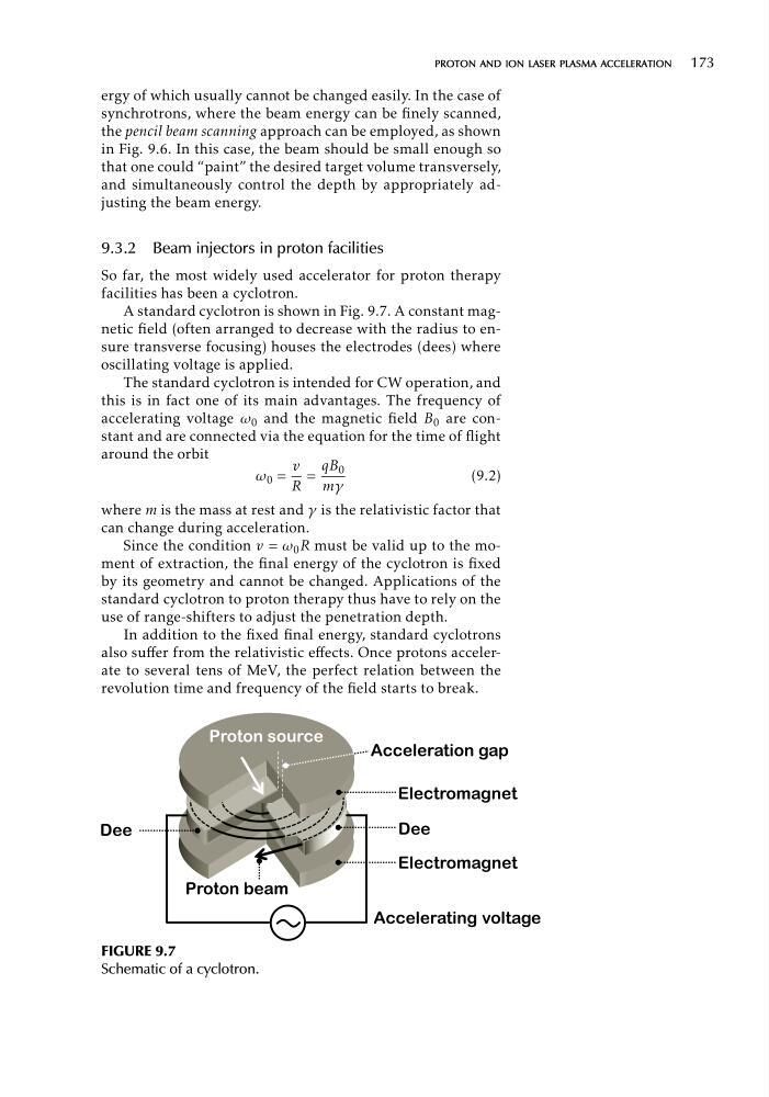
A standard cyclotron is shown in Fig. 9.7. A constant magnetic field (often arranged to decrease with the radius to ensure transverse focusing) houses the electrodes (dees) where
oscillating voltage is applied.
The standard cyclotron is intended for CW operation, and
this is in fact one of its main advantages. The frequency of
accelerating voltage ω 0 and the magnetic field B 0 are constant and are connected via the equation for the time of flight
around the orbit
v qB 0
ω 0 = =
(9.2)
R mγ
where m is the mass at rest and γ is the relativistic factor that
can change during acceleration.
Since the condition v = ω 0 R must be valid up to the moment of extraction, the final energy of the cyclotron is fixed
by its geometry and cannot be changed. Applications of the
standard cyclotron to proton therapy thus have to rely on the
use of range-shifters to adjust the penetration depth.
In addition to the fixed final energy, standard cyclotrons
also suffer from the relativistic effects. Once protons accelerate to several tens of MeV, the perfect relation between the
revolution time and frequency of the field starts to break.
FIGURE 9.7
Schematic of a cyclotron.
ergy of which usually cannot be changed easily. In the case of
synchrotrons, where the beam energy can be finely scanned,
the pencil beam scanning approach can be employed, as shown
in Fig. 9.6. In this case, the beam should be small enough so
that one could “paint” the desired target volume transversely,
and simultaneously control the depth by appropriately adjusting the beam energy.
9.3.2 Beam injectors in proton facilities
So far, the most widely used accelerator for proton therapy
facilities has been a cyclotron.
A standard cyclotron is shown in Fig. 9.7. A constant magnetic field (often arranged to decrease with the radius to ensure transverse focusing) houses the electrodes (dees) where
oscillating voltage is applied.
The standard cyclotron is intended for CW operation, and
this is in fact one of its main advantages. The frequency of
accelerating voltage ω 0 and the magnetic field B 0 are constant and are connected via the equation for the time of flight
around the orbit
v qB 0
ω 0 = =
(9.2)
R mγ
where m is the mass at rest and γ is the relativistic factor that
can change during acceleration.
Since the condition v = ω 0 R must be valid up to the moment of extraction, the final energy of the cyclotron is fixed
by its geometry and cannot be changed. Applications of the
standard cyclotron to proton therapy thus have to rely on the
use of range-shifters to adjust the penetration depth.
In addition to the fixed final energy, standard cyclotrons
also suffer from the relativistic effects. Once protons accelerate to several tens of MeV, the perfect relation between the
revolution time and frequency of the field starts to break.
FIGURE 9.7
Schematic of a cyclotron.