

D
FIGURE 5.17
Intermediate case.
84 unifying physics of accelerators, lasers and plasma
In the intermediate region of frequencies, the dispersion
curve should connect the point (ii) and region (i) in Fig.5.16.
Looking at the wave in a waveguide from a simple geometrical point of view (Fig.5.17) and considering corresponding
similar triangles, one can write
2
ω c
2
ω = k
2 +
(5.12)
c
c
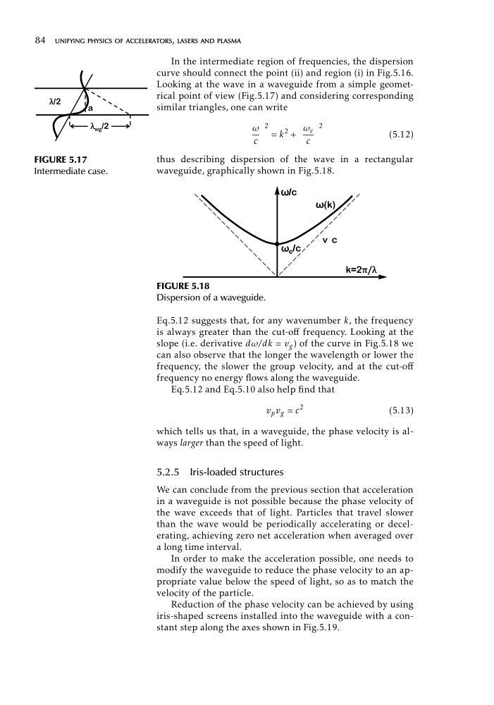
thus describing dispersion of the wave in a rectangular
waveguide, graphically shown in Fig.5.18.
F
N
Y F
N
F
FIGURE 5.18
Dispersion of a waveguide.
Eq.5.12 suggests that, for any wavenumber k, the frequency
is always greater than the cut-off frequency. Looking at the
slope (i.e. derivative dω/dk = v g ) of the curve in Fig.5.18 we
can also observe that the longer the wavelength or lower the
frequency, the slower the group velocity, and at the cut-off
frequency no energy flows along the waveguide.
Eq.5.12 and Eq.5.10 also help find that
2
v p v g = c
(5.13)
which tells us that, in a waveguide, the phase velocity is always larger than the speed of light.
5.2.5 Iris-loaded structures
We can conclude from the previous section that acceleration
in a waveguide is not possible because the phase velocity of
the wave exceeds that of light. Particles that travel slower
than the wave would be periodically accelerating or decelerating, achieving zero net acceleration when averaged over
a long time interval.
In order to make the acceleration possible, one needs to
modify the waveguide to reduce the phase velocity to an appropriate value below the speed of light, so as to match the
velocity of the particle.
Reduction of the phase velocity can be achieved by using
iris-shaped screens installed into the waveguide with a constant step along the axes shown in Fig.5.19.
FIGURE 5.17
Intermediate case.
84 unifying physics of accelerators, lasers and plasma
In the intermediate region of frequencies, the dispersion
curve should connect the point (ii) and region (i) in Fig.5.16.
Looking at the wave in a waveguide from a simple geometrical point of view (Fig.5.17) and considering corresponding
similar triangles, one can write
2
ω c
2
ω = k
2 +
(5.12)
c
c
thus describing dispersion of the wave in a rectangular
waveguide, graphically shown in Fig.5.18.
F
N
Y F
N
F
FIGURE 5.18
Dispersion of a waveguide.
Eq.5.12 suggests that, for any wavenumber k, the frequency
is always greater than the cut-off frequency. Looking at the
slope (i.e. derivative dω/dk = v g ) of the curve in Fig.5.18 we
can also observe that the longer the wavelength or lower the
frequency, the slower the group velocity, and at the cut-off
frequency no energy flows along the waveguide.
Eq.5.12 and Eq.5.10 also help find that
2
v p v g = c
(5.13)
which tells us that, in a waveguide, the phase velocity is always larger than the speed of light.
5.2.5 Iris-loaded structures
We can conclude from the previous section that acceleration
in a waveguide is not possible because the phase velocity of
the wave exceeds that of light. Particles that travel slower
than the wave would be periodically accelerating or decelerating, achieving zero net acceleration when averaged over
a long time interval.
In order to make the acceleration possible, one needs to
modify the waveguide to reduce the phase velocity to an appropriate value below the speed of light, so as to match the
velocity of the particle.
Reduction of the phase velocity can be achieved by using
iris-shaped screens installed into the waveguide with a constant step along the axes shown in Fig.5.19.