

Beams and Beam Physics
27
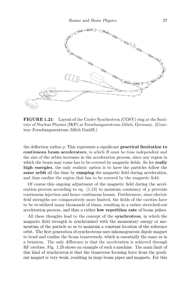
FIGURE 1.21: Layout of the Cooler Synchrotron (COSY) ring at the Institute of Nuclear Physics (IKP) at Forschungszentrum J¨ ulich, Germany. (Courtesy Forschungszentrum J¨ ulich GmbH.)
the deflection radius ρ. This represents a significant practical limitation to
continuous beam accelerators, in which B must be time independent and
the size of the orbits increases in the acceleration process, since any region in
which the beam may come has to be covered by magnetic fields. So for really
high energies, the only realistic option is to have the particles follow the
same orbit all the time by ramping the magnetic field during acceleration,
and thus confine the region that has to be covered by the magnetic field.
Of course this ongoing adjustment of the magnetic field during the acceleration process according to eq. (1.13) to maintain constancy of ρ prevents
continuous injection and hence continuous beams. Furthermore, since electric
field strengths are comparatively more limited, the fields of the cavities have
to be re-utilized many thousands of times, resulting in a rather stretched-out
acceleration process, and thus a rather low repetition rate of beam pulses.
All these thoughts lead to the concept of the synchrotron, in which the
magnetic field strength is synchronized with the momentary energy or momentum of the particle so as to maintain a constant location of the reference
orbit. The first generation of synchrotrons uses inhomogeneous dipole magnet
to bend and confine the beam transversely, which is essentially the same as in
a betatron. The only difference is that the acceleration is achieved through
RF cavities. Fig. 1.20 shows an example of such a machine. The main limit of
this kind of synchrotron is that the transverse focusing force from the gradient magnet is very weak, resulting in large beam pipes and magnets. For this
27
FIGURE 1.21: Layout of the Cooler Synchrotron (COSY) ring at the Institute of Nuclear Physics (IKP) at Forschungszentrum J¨ ulich, Germany. (Courtesy Forschungszentrum J¨ ulich GmbH.)
the deflection radius ρ. This represents a significant practical limitation to
continuous beam accelerators, in which B must be time independent and
the size of the orbits increases in the acceleration process, since any region in
which the beam may come has to be covered by magnetic fields. So for really
high energies, the only realistic option is to have the particles follow the
same orbit all the time by ramping the magnetic field during acceleration,
and thus confine the region that has to be covered by the magnetic field.
Of course this ongoing adjustment of the magnetic field during the acceleration process according to eq. (1.13) to maintain constancy of ρ prevents
continuous injection and hence continuous beams. Furthermore, since electric
field strengths are comparatively more limited, the fields of the cavities have
to be re-utilized many thousands of times, resulting in a rather stretched-out
acceleration process, and thus a rather low repetition rate of beam pulses.
All these thoughts lead to the concept of the synchrotron, in which the
magnetic field strength is synchronized with the momentary energy or momentum of the particle so as to maintain a constant location of the reference
orbit. The first generation of synchrotrons uses inhomogeneous dipole magnet
to bend and confine the beam transversely, which is essentially the same as in
a betatron. The only difference is that the acceleration is achieved through
RF cavities. Fig. 1.20 shows an example of such a machine. The main limit of
this kind of synchrotron is that the transverse focusing force from the gradient magnet is very weak, resulting in large beam pipes and magnets. For this