

Beams and Beam Physics
17
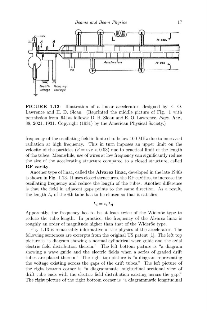
FIGURE 1.12: Illustration of a linear accelerator, designed by E. O.
Lawrence and H. D. Sloan. (Reprinted the middle picture of Fig. 1 with
permission from [64] as follows: D. H. Sloan and E. O. Lawrence, Phys. Rev.,
38, 2021, 1931. Copyright (1931) by the American Physical Society.)
frequency of the oscillating field is limited to below 100 MHz due to increased
radiation at high frequency. This in turn imposes an upper limit on the
velocity of the particles (β = v/c < 0.03) due to practical limit of the length
of the tubes. Meanwhile, use of wires at low frequency can significantly reduce
the size of the accelerating structure compared to a closed structure, called
RF cavity.
Another type of linac, called the Alvarez linac, developed in the late 1940s
is shown in Fig. 1.13. It uses closed structures, the RF cavities, to increase the
oscillating frequency and reduce the length of the tubes. Another difference
is that the field in adjacent gaps points to the same direction. As a result,
the length L i of the ith tube has to be chosen so that it satisfies
L i = v i T rf .
Apparently, the frequency has to be at least twice of the Wider¨ oe type to
reduce the tube length. In practice, the frequency of the Alvarez linac is
roughly an order of magnitude higher than that of the Wider¨ oe type.
Fig. 1.13 is remarkably informative of the physics of the accelerator. The
following sentences are excerpts from the original US patent [1]. The left top
picture is “a diagram showing a normal cylindrical wave guide and the axial
electric field distribution therein.” The left bottom picture is “a diagram
showing a wave guide and the electric fields when a series of graded drift
tubes are placed therein.” The right top picture is “a diagram representing
the voltage existing across the gaps of the drift tubes.” The left picture of
the right bottom corner is “a diagrammatic longitudinal sectional view of
drift tube ends with the electric field distribution existing across the gap.”
The right picture of the right bottom corner is “a diagrammatic longitudinal
17
FIGURE 1.12: Illustration of a linear accelerator, designed by E. O.
Lawrence and H. D. Sloan. (Reprinted the middle picture of Fig. 1 with
permission from [64] as follows: D. H. Sloan and E. O. Lawrence, Phys. Rev.,
38, 2021, 1931. Copyright (1931) by the American Physical Society.)
frequency of the oscillating field is limited to below 100 MHz due to increased
radiation at high frequency. This in turn imposes an upper limit on the
velocity of the particles (β = v/c < 0.03) due to practical limit of the length
of the tubes. Meanwhile, use of wires at low frequency can significantly reduce
the size of the accelerating structure compared to a closed structure, called
RF cavity.
Another type of linac, called the Alvarez linac, developed in the late 1940s
is shown in Fig. 1.13. It uses closed structures, the RF cavities, to increase the
oscillating frequency and reduce the length of the tubes. Another difference
is that the field in adjacent gaps points to the same direction. As a result,
the length L i of the ith tube has to be chosen so that it satisfies
L i = v i T rf .
Apparently, the frequency has to be at least twice of the Wider¨ oe type to
reduce the tube length. In practice, the frequency of the Alvarez linac is
roughly an order of magnitude higher than that of the Wider¨ oe type.
Fig. 1.13 is remarkably informative of the physics of the accelerator. The
following sentences are excerpts from the original US patent [1]. The left top
picture is “a diagram showing a normal cylindrical wave guide and the axial
electric field distribution therein.” The left bottom picture is “a diagram
showing a wave guide and the electric fields when a series of graded drift
tubes are placed therein.” The right top picture is “a diagram representing
the voltage existing across the gaps of the drift tubes.” The left picture of
the right bottom corner is “a diagrammatic longitudinal sectional view of
drift tube ends with the electric field distribution existing across the gap.”
The right picture of the right bottom corner is “a diagrammatic longitudinal