

Lattice Modules
237
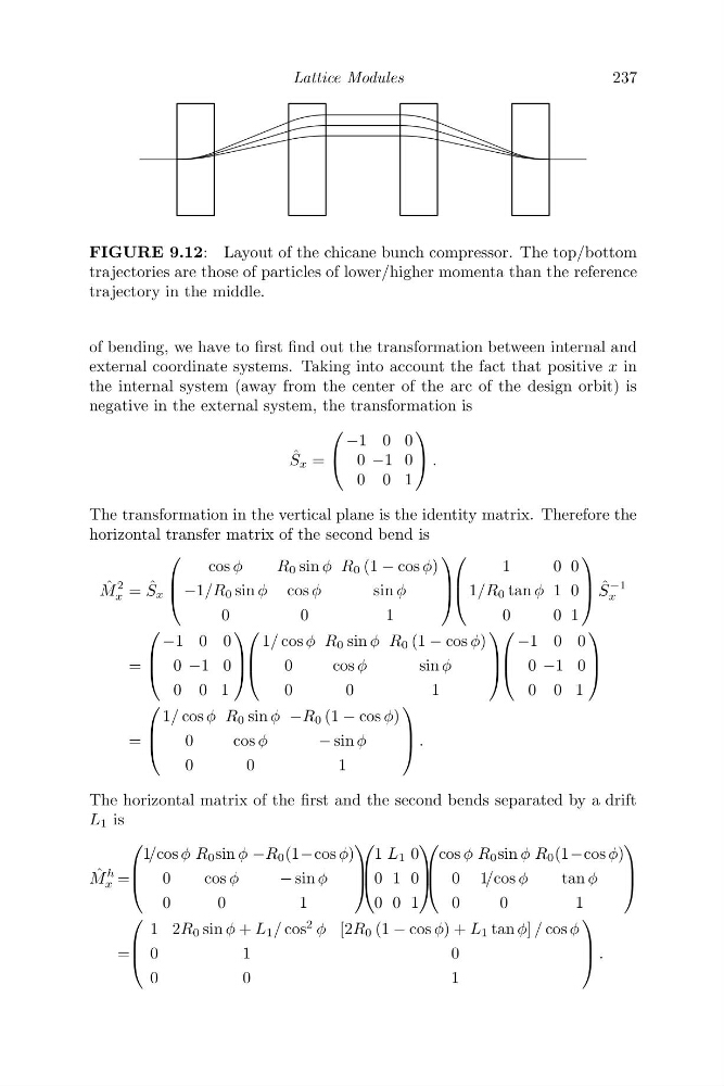
FIGURE 9.12: Layout of the chicane bunch compressor. The top/bottom
trajectories are those of particles of lower/higher momenta than the reference
trajectory in the middle.
of bending, we have to first find out the transformation between internal and
external coordinate systems. Taking into account the fact that positive x in
the internal system (away from the center of the arc of the design orbit) is
negative in the external system, the transformation is
ˆ
S x =
⎛
⎝
−1 0 0
0 −1 0
0 0 1
⎞
⎠ .
The transformation in the vertical plane is the identity matrix. Therefore the
horizontal transfer matrix of the second bend is
ˆ
M
2
x = ˆ
S x
⎛
⎜
⎝
cos φ
R 0 sin φ R 0 (1 − cos φ)
−1/R 0 sin φ cos φ
sin φ
0
0
1
⎞
⎟
⎠
⎛
⎜
⎝
1
0 0
1/R 0 tan φ 1 0
0
0 1
⎞
⎟
⎠ ˆ
S
−1
x
=
⎛
⎜
⎝
−1 0 0
0 −1 0
0 0 1
⎞
⎟
⎠
⎛
⎜
⎝
1/ cos φ R 0 sin φ R 0 (1 − cos φ)
0
cosφ
sin φ
0
0
1
⎞
⎟
⎠
⎛
⎜
⎝
−1 0 0
0 −1 0
0 0 1
⎞
⎟
⎠
=
⎛
⎜
⎝
1/ cos φ R 0 sin φ −R 0 (1 − cos φ)
0
cosφ
− sin φ
0
0
1
⎞
⎟
⎠ .
The horizontal matrix of the first and the second bends separated by a drift
L 1 is
ˆ
M
h
x =
⎛
⎜
⎝
1/cos φ R 0 sin φ −R 0 (1−cos φ)
0
cosφ
− sin φ
0
0
1
⎞
⎟
⎠
⎛
⎜
⎝
1 L 1 0
0 1 0
0 0 1
⎞
⎟
⎠
⎛
⎜
⎝
cos φ R 0 sin φ R 0 (1−cos φ)
0 1/cos φ
tan φ
0
0
1
⎞
⎟
⎠
=
⎛
⎜
⎝
1 2R 0 sin φ + L 1 / cos
2 φ [2R 0 (1 − cos φ) + L 1 tan φ] / cos φ
0
1
0
0
0
1
⎞
⎟
⎠ .
237
FIGURE 9.12: Layout of the chicane bunch compressor. The top/bottom
trajectories are those of particles of lower/higher momenta than the reference
trajectory in the middle.
of bending, we have to first find out the transformation between internal and
external coordinate systems. Taking into account the fact that positive x in
the internal system (away from the center of the arc of the design orbit) is
negative in the external system, the transformation is
ˆ
S x =
⎛
⎝
−1 0 0
0 −1 0
0 0 1
⎞
⎠ .
The transformation in the vertical plane is the identity matrix. Therefore the
horizontal transfer matrix of the second bend is
ˆ
M
2
x = ˆ
S x
⎛
⎜
⎝
cos φ
R 0 sin φ R 0 (1 − cos φ)
−1/R 0 sin φ cos φ
sin φ
0
0
1
⎞
⎟
⎠
⎛
⎜
⎝
1
0 0
1/R 0 tan φ 1 0
0
0 1
⎞
⎟
⎠ ˆ
S
−1
x
=
⎛
⎜
⎝
−1 0 0
0 −1 0
0 0 1
⎞
⎟
⎠
⎛
⎜
⎝
1/ cos φ R 0 sin φ R 0 (1 − cos φ)
0
cosφ
sin φ
0
0
1
⎞
⎟
⎠
⎛
⎜
⎝
−1 0 0
0 −1 0
0 0 1
⎞
⎟
⎠
=
⎛
⎜
⎝
1/ cos φ R 0 sin φ −R 0 (1 − cos φ)
0
cosφ
− sin φ
0
0
1
⎞
⎟
⎠ .
The horizontal matrix of the first and the second bends separated by a drift
L 1 is
ˆ
M
h
x =
⎛
⎜
⎝
1/cos φ R 0 sin φ −R 0 (1−cos φ)
0
cosφ
− sin φ
0
0
1
⎞
⎟
⎠
⎛
⎜
⎝
1 L 1 0
0 1 0
0 0 1
⎞
⎟
⎠
⎛
⎜
⎝
cos φ R 0 sin φ R 0 (1−cos φ)
0 1/cos φ
tan φ
0
0
1
⎞
⎟
⎠
=
⎛
⎜
⎝
1 2R 0 sin φ + L 1 / cos
2 φ [2R 0 (1 − cos φ) + L 1 tan φ] / cos φ
0
1
0
0
0
1
⎞
⎟
⎠ .