

186
An Introduction to Beam Physics
Q
L
Q
Q
L
Q
Q
L
Q
D
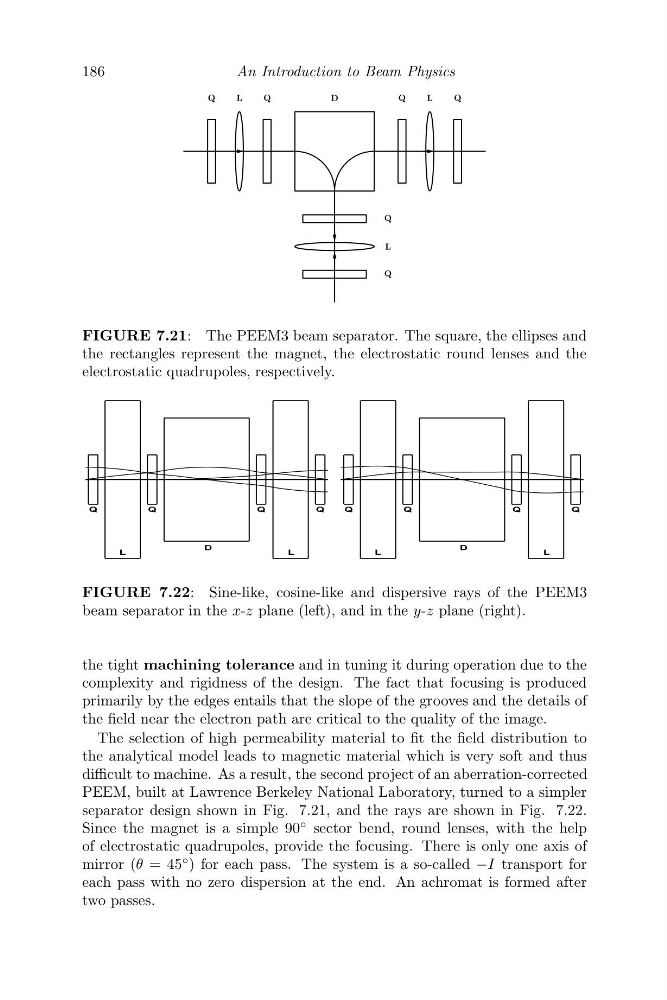
FIGURE 7.21: The PEEM3 beam separator. The square, the ellipses and
the rectangles represent the magnet, the electrostatic round lenses and the
electrostatic quadrupoles, respectively.
4
/
4
'
4
/
4
4
/
4
'
4
/
4
FIGURE 7.22: Sine-like, cosine-like and dispersive rays of the PEEM3
beam separator in the x-z plane (left), and in the y-z plane (right).
the tight machining tolerance and in tuning it during operation due to the
complexity and rigidness of the design. The fact that focusing is produced
primarily by the edges entails that the slope of the grooves and the details of
the field near the electron path are critical to the quality of the image.
The selection of high permeability material to fit the field distribution to
the analytical model leads to magnetic material which is very soft and thus
difficult to machine. As a result, the second project of an aberration-corrected
PEEM, built at Lawrence Berkeley National Laboratory, turned to a simpler
separator design shown in Fig. 7.21, and the rays are shown in Fig. 7.22.
Since the magnet is a simple 90
◦ sector bend, round lenses, with the help
of electrostatic quadrupoles, provide the focusing. There is only one axis of
mirror (θ = 45
◦ ) for each pass. The system is a so-called −I transport for
each pass with no zero dispersion at the end. An achromat is formed after
two passes.
An Introduction to Beam Physics
Q
L
Q
Q
L
Q
Q
L
Q
D
FIGURE 7.21: The PEEM3 beam separator. The square, the ellipses and
the rectangles represent the magnet, the electrostatic round lenses and the
electrostatic quadrupoles, respectively.
4
/
4
'
4
/
4
4
/
4
'
4
/
4
FIGURE 7.22: Sine-like, cosine-like and dispersive rays of the PEEM3
beam separator in the x-z plane (left), and in the y-z plane (right).
the tight machining tolerance and in tuning it during operation due to the
complexity and rigidness of the design. The fact that focusing is produced
primarily by the edges entails that the slope of the grooves and the details of
the field near the electron path are critical to the quality of the image.
The selection of high permeability material to fit the field distribution to
the analytical model leads to magnetic material which is very soft and thus
difficult to machine. As a result, the second project of an aberration-corrected
PEEM, built at Lawrence Berkeley National Laboratory, turned to a simpler
separator design shown in Fig. 7.21, and the rays are shown in Fig. 7.22.
Since the magnet is a simple 90
◦ sector bend, round lenses, with the help
of electrostatic quadrupoles, provide the focusing. There is only one axis of
mirror (θ = 45
◦ ) for each pass. The system is a so-called −I transport for
each pass with no zero dispersion at the end. An achromat is formed after
two passes.