

Imaging Devices
185
E
6
6
6
D
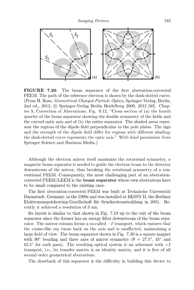
FIGURE 7.20: The beam separator of the first aberration-corrected
PEEM. The path of the reference electron is shown by the dash-dotted curve.
(From H. Rose, Geometrical Charged-Particle Optics, Springer-Verlag, Berlin,
2nd ed., 2012, c
Springer-Verlag Berlin Heidelberg 2009, 2012 [60]. Chapter 9, Correction of Aberrations, Fig. 9.12, “Cross section of (a) the fourth
quarter of the beam separator showing the double symmetry of the fields and
the curved optic axis and of (b) the entire separator. The shaded areas represent the regions of the dipole field perpendicular to the pole plates. The sign
and the strength of the dipole field differ for regions with different shading;
the dash-dotted curve represents the optic axis.” With kind permission from
Springer Science and Business Media.)
Although the electron mirror itself maintains the rotational symmetry, a
magnetic beam separator is needed to guide the electron beam to the detector
downstream of the mirror, thus breaking the rotational symmetry of a conventional PEEM. Consequently, the most challenging part of an aberrationcorrected PEEM/LEEM is the beam separator whose own aberrations have
to be small compared to the existing ones.
The first aberration-corrected PEEM was built at Technische Universit¨ at
Darmstadt, Germany, in the 1990s and was installed at BESSY II, the Berliner
Elektronenspeicherring-Gesellschaft f¨ ur Synchrotronstrahlung in 2001. Recently it achieved a resolution of 3 nm.
Its layout is similar to that shown in Fig. 7.19 up to the exit of the beam
separator since the former has an energy filter downstream of the beam separator. The mirror column forms a so-called −I transport, which ensures that
the cosine-like ray turns back on the axis and is unaffected, maintaining a
large field of view. The beam separator shown in Fig. 7.20 is a square magnet
with 90 ◦ bending and three axes of mirror symmetry (θ = 27.5
◦ , 45
◦ and
62.5
◦ for each pass). The resulting optical system is an achromat with +I
transport, i.e., its transfer matrix is an identity matrix, and it is free of all
second order geometrical aberrations.
The drawback of this separator is the difficulty in building this device to
185
E
6
6
6
D
FIGURE 7.20: The beam separator of the first aberration-corrected
PEEM. The path of the reference electron is shown by the dash-dotted curve.
(From H. Rose, Geometrical Charged-Particle Optics, Springer-Verlag, Berlin,
2nd ed., 2012, c
Springer-Verlag Berlin Heidelberg 2009, 2012 [60]. Chapter 9, Correction of Aberrations, Fig. 9.12, “Cross section of (a) the fourth
quarter of the beam separator showing the double symmetry of the fields and
the curved optic axis and of (b) the entire separator. The shaded areas represent the regions of the dipole field perpendicular to the pole plates. The sign
and the strength of the dipole field differ for regions with different shading;
the dash-dotted curve represents the optic axis.” With kind permission from
Springer Science and Business Media.)
Although the electron mirror itself maintains the rotational symmetry, a
magnetic beam separator is needed to guide the electron beam to the detector
downstream of the mirror, thus breaking the rotational symmetry of a conventional PEEM. Consequently, the most challenging part of an aberrationcorrected PEEM/LEEM is the beam separator whose own aberrations have
to be small compared to the existing ones.
The first aberration-corrected PEEM was built at Technische Universit¨ at
Darmstadt, Germany, in the 1990s and was installed at BESSY II, the Berliner
Elektronenspeicherring-Gesellschaft f¨ ur Synchrotronstrahlung in 2001. Recently it achieved a resolution of 3 nm.
Its layout is similar to that shown in Fig. 7.19 up to the exit of the beam
separator since the former has an energy filter downstream of the beam separator. The mirror column forms a so-called −I transport, which ensures that
the cosine-like ray turns back on the axis and is unaffected, maintaining a
large field of view. The beam separator shown in Fig. 7.20 is a square magnet
with 90 ◦ bending and three axes of mirror symmetry (θ = 27.5
◦ , 45
◦ and
62.5
◦ for each pass). The resulting optical system is an achromat with +I
transport, i.e., its transfer matrix is an identity matrix, and it is free of all
second order geometrical aberrations.
The drawback of this separator is the difficulty in building this device to