

184
An Introduction to Beam Physics
]PP
UPP
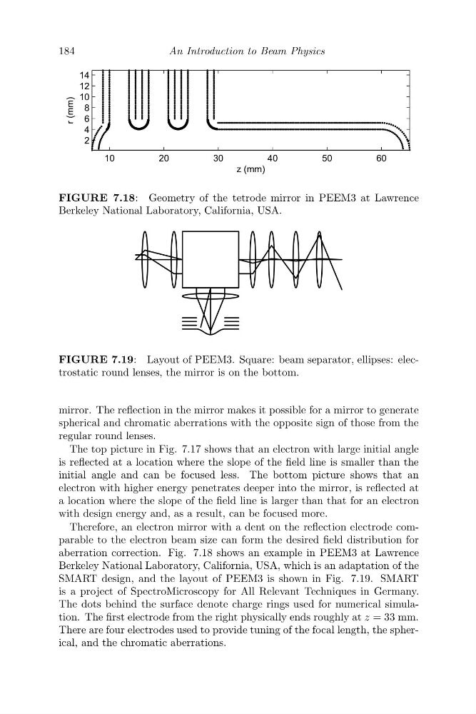
FIGURE 7.18: Geometry of the tetrode mirror in PEEM3 at Lawrence
Berkeley National Laboratory, California, USA.
FIGURE 7.19: Layout of PEEM3. Square: beam separator, ellipses: electrostatic round lenses, the mirror is on the bottom.
mirror. The reflection in the mirror makes it possible for a mirror to generate
spherical and chromatic aberrations with the opposite sign of those from the
regular round lenses.
The top picture in Fig. 7.17 shows that an electron with large initial angle
is reflected at a location where the slope of the field line is smaller than the
initial angle and can be focused less. The bottom picture shows that an
electron with higher energy penetrates deeper into the mirror, is reflected at
a location where the slope of the field line is larger than that for an electron
with design energy and, as a result, can be focused more.
Therefore, an electron mirror with a dent on the reflection electrode comparable to the electron beam size can form the desired field distribution for
aberration correction. Fig. 7.18 shows an example in PEEM3 at Lawrence
Berkeley National Laboratory, California, USA, which is an adaptation of the
SMART design, and the layout of PEEM3 is shown in Fig. 7.19. SMART
is a project of SpectroMicroscopy for All Relevant Techniques in Germany.
The dots behind the surface denote charge rings used for numerical simulation. The first electrode from the right physically ends roughly at z = 33 mm.
There are four electrodes used to provide tuning of the focal length, the spherical, and the chromatic aberrations.
An Introduction to Beam Physics
]PP
UPP
FIGURE 7.18: Geometry of the tetrode mirror in PEEM3 at Lawrence
Berkeley National Laboratory, California, USA.
FIGURE 7.19: Layout of PEEM3. Square: beam separator, ellipses: electrostatic round lenses, the mirror is on the bottom.
mirror. The reflection in the mirror makes it possible for a mirror to generate
spherical and chromatic aberrations with the opposite sign of those from the
regular round lenses.
The top picture in Fig. 7.17 shows that an electron with large initial angle
is reflected at a location where the slope of the field line is smaller than the
initial angle and can be focused less. The bottom picture shows that an
electron with higher energy penetrates deeper into the mirror, is reflected at
a location where the slope of the field line is larger than that for an electron
with design energy and, as a result, can be focused more.
Therefore, an electron mirror with a dent on the reflection electrode comparable to the electron beam size can form the desired field distribution for
aberration correction. Fig. 7.18 shows an example in PEEM3 at Lawrence
Berkeley National Laboratory, California, USA, which is an adaptation of the
SMART design, and the layout of PEEM3 is shown in Fig. 7.19. SMART
is a project of SpectroMicroscopy for All Relevant Techniques in Germany.
The dots behind the surface denote charge rings used for numerical simulation. The first electrode from the right physically ends roughly at z = 33 mm.
There are four electrodes used to provide tuning of the focal length, the spherical, and the chromatic aberrations.