

Imaging Devices
183
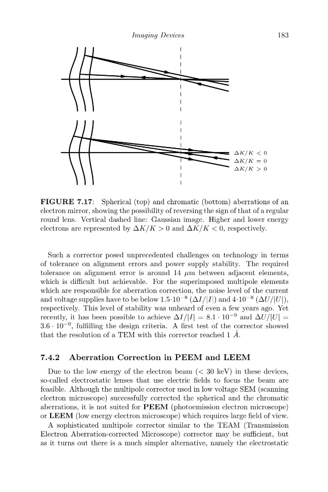
ΔK/K > 0
ΔK/K = 0
ΔK/K < 0
FIGURE 7.17: Spherical (top) and chromatic (bottom) aberrations of an
electron mirror, showing the possibility of reversing the sign of that of a regular
round lens. Vertical dashed line: Gaussian image. Higher and lower energy
electrons are represented by ΔK/K > 0 and ΔK/K < 0, respectively.
Such a corrector posed unprecedented challenges on technology in terms
of tolerance on alignment errors and power supply stability. The required
tolerance on alignment error is around 14 μm between adjacent elements,
which is difficult but achievable. For the superimposed multipole elements
which are responsible for aberration correction, the noise level of the current
and voltage supplies have to be below 1.5·10
−8 (ΔI/|I|) and 4·10
−8 (ΔU/|U |),
respectively. This level of stability was unheard of even a few years ago. Yet
recently, it has been possible to achieve ΔI/|I| = 8.1 · 10
−9 and ΔU/|U | =
3.6 · 10
−9 , fulfilling the design criteria. A first test of the corrector showed
that the resolution of a TEM with this corrector reached 1 ˚
A.
7.4.2 Aberration Correction in PEEM and LEEM
Due to the low energy of the electron beam (< 30 keV) in these devices,
so-called electrostatic lenses that use electric fields to focus the beam are
feasible. Although the multipole corrector used in low voltage SEM (scanning
electron microscope) successfully corrected the spherical and the chromatic
aberrations, it is not suited for PEEM (photoemission electron microscope)
or LEEM (low energy electron microscope) which requires large field of view.
A sophisticated multipole corrector similar to the TEAM (Transmission
Electron Aberration-corrected Microscope) corrector may be sufficient, but
as it turns out there is a much simpler alternative, namely the electrostatic
183
ΔK/K > 0
ΔK/K = 0
ΔK/K < 0
FIGURE 7.17: Spherical (top) and chromatic (bottom) aberrations of an
electron mirror, showing the possibility of reversing the sign of that of a regular
round lens. Vertical dashed line: Gaussian image. Higher and lower energy
electrons are represented by ΔK/K > 0 and ΔK/K < 0, respectively.
Such a corrector posed unprecedented challenges on technology in terms
of tolerance on alignment errors and power supply stability. The required
tolerance on alignment error is around 14 μm between adjacent elements,
which is difficult but achievable. For the superimposed multipole elements
which are responsible for aberration correction, the noise level of the current
and voltage supplies have to be below 1.5·10
−8 (ΔI/|I|) and 4·10
−8 (ΔU/|U |),
respectively. This level of stability was unheard of even a few years ago. Yet
recently, it has been possible to achieve ΔI/|I| = 8.1 · 10
−9 and ΔU/|U | =
3.6 · 10
−9 , fulfilling the design criteria. A first test of the corrector showed
that the resolution of a TEM with this corrector reached 1 ˚
A.
7.4.2 Aberration Correction in PEEM and LEEM
Due to the low energy of the electron beam (< 30 keV) in these devices,
so-called electrostatic lenses that use electric fields to focus the beam are
feasible. Although the multipole corrector used in low voltage SEM (scanning
electron microscope) successfully corrected the spherical and the chromatic
aberrations, it is not suited for PEEM (photoemission electron microscope)
or LEEM (low energy electron microscope) which requires large field of view.
A sophisticated multipole corrector similar to the TEAM (Transmission
Electron Aberration-corrected Microscope) corrector may be sufficient, but
as it turns out there is a much simpler alternative, namely the electrostatic