

182
An Introduction to Beam Physics
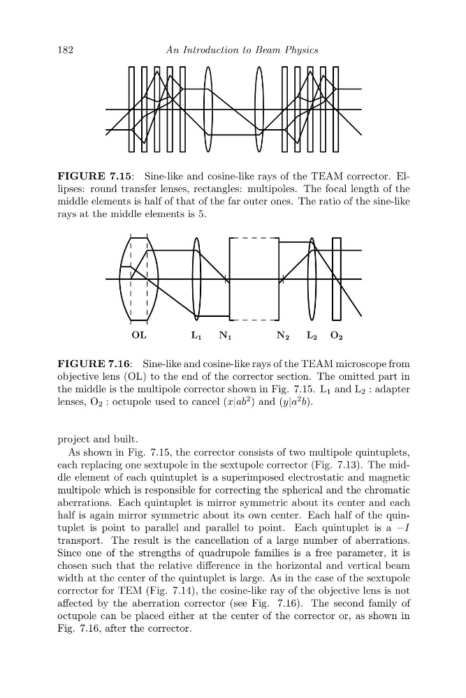
FIGURE 7.15: Sine-like and cosine-like rays of the TEAM corrector. Ellipses: round transfer lenses, rectangles: multipoles. The focal length of the
middle elements is half of that of the far outer ones. The ratio of the sine-like
rays at the middle elements is 5.
OL
N 1
N 2
L 1
L 2 O 2
FIGURE 7.16: Sine-like and cosine-like rays of the TEAM microscope from
objective lens (OL) to the end of the corrector section. The omitted part in
the middle is the multipole corrector shown in Fig. 7.15. L 1 and L 2 : adapter
lenses, O 2 : octupole used to cancel (x|ab
2 ) and (y|a
2 b).
project and built.
As shown in Fig. 7.15, the corrector consists of two multipole quintuplets,
each replacing one sextupole in the sextupole corrector (Fig. 7.13). The middle element of each quintuplet is a superimposed electrostatic and magnetic
multipole which is responsible for correcting the spherical and the chromatic
aberrations. Each quintuplet is mirror symmetric about its center and each
half is again mirror symmetric about its own center. Each half of the quintuplet is point to parallel and parallel to point. Each quintuplet is a −I
transport. The result is the cancellation of a large number of aberrations.
Since one of the strengths of quadrupole families is a free parameter, it is
chosen such that the relative difference in the horizontal and vertical beam
width at the center of the quintuplet is large. As in the case of the sextupole
corrector for TEM (Fig. 7.14), the cosine-like ray of the objective lens is not
affected by the aberration corrector (see Fig. 7.16). The second family of
octupole can be placed either at the center of the corrector or, as shown in
Fig. 7.16, after the corrector.
An Introduction to Beam Physics
FIGURE 7.15: Sine-like and cosine-like rays of the TEAM corrector. Ellipses: round transfer lenses, rectangles: multipoles. The focal length of the
middle elements is half of that of the far outer ones. The ratio of the sine-like
rays at the middle elements is 5.
OL
N 1
N 2
L 1
L 2 O 2
FIGURE 7.16: Sine-like and cosine-like rays of the TEAM microscope from
objective lens (OL) to the end of the corrector section. The omitted part in
the middle is the multipole corrector shown in Fig. 7.15. L 1 and L 2 : adapter
lenses, O 2 : octupole used to cancel (x|ab
2 ) and (y|a
2 b).
project and built.
As shown in Fig. 7.15, the corrector consists of two multipole quintuplets,
each replacing one sextupole in the sextupole corrector (Fig. 7.13). The middle element of each quintuplet is a superimposed electrostatic and magnetic
multipole which is responsible for correcting the spherical and the chromatic
aberrations. Each quintuplet is mirror symmetric about its center and each
half is again mirror symmetric about its own center. Each half of the quintuplet is point to parallel and parallel to point. Each quintuplet is a −I
transport. The result is the cancellation of a large number of aberrations.
Since one of the strengths of quadrupole families is a free parameter, it is
chosen such that the relative difference in the horizontal and vertical beam
width at the center of the quintuplet is large. As in the case of the sextupole
corrector for TEM (Fig. 7.14), the cosine-like ray of the objective lens is not
affected by the aberration corrector (see Fig. 7.16). The second family of
octupole can be placed either at the center of the corrector or, as shown in
Fig. 7.16, after the corrector.