

Imaging Devices
187
sample
contrast
aperture
gun
mirror
screen
electrostatic lens
magnetic lens
axial ray
field ray
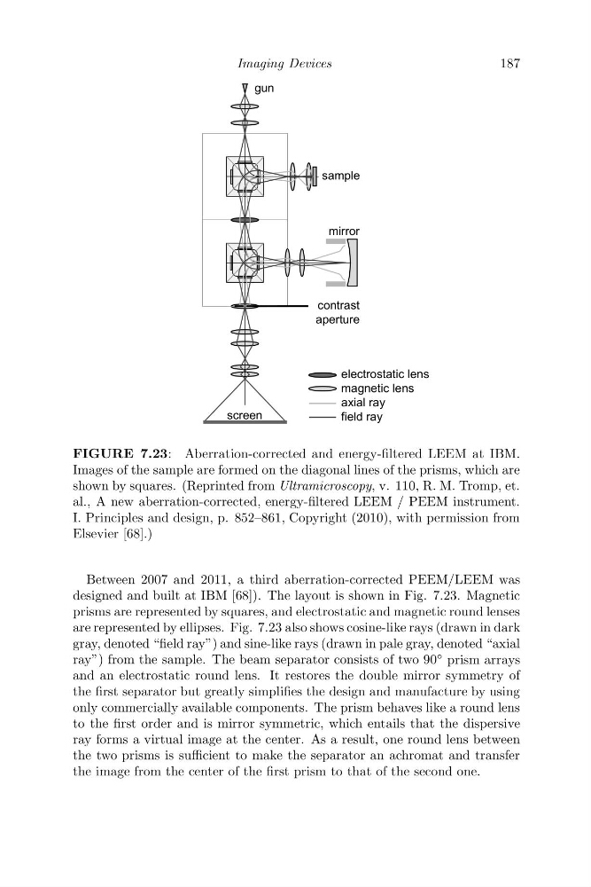
FIGURE 7.23: Aberration-corrected and energy-filtered LEEM at IBM.
Images of the sample are formed on the diagonal lines of the prisms, which are
shown by squares. (Reprinted from Ultramicroscopy, v. 110, R. M. Tromp, et.
al., A new aberration-corrected, energy-filtered LEEM / PEEM instrument.
I. Principles and design, p. 852–861, Copyright (2010), with permission from
Elsevier [68].)
Between 2007 and 2011, a third aberration-corrected PEEM/LEEM was
designed and built at IBM [68]). The layout is shown in Fig. 7.23. Magnetic
prisms are represented by squares, and electrostatic and magnetic round lenses
are represented by ellipses. Fig. 7.23 also shows cosine-like rays (drawn in dark
gray, denoted “field ray”) and sine-like rays (drawn in pale gray, denoted “axial
ray”) from the sample. The beam separator consists of two 90
◦ prism arrays
and an electrostatic round lens. It restores the double mirror symmetry of
the first separator but greatly simplifies the design and manufacture by using
only commercially available components. The prism behaves like a round lens
to the first order and is mirror symmetric, which entails that the dispersive
ray forms a virtual image at the center. As a result, one round lens between
the two prisms is sufficient to make the separator an achromat and transfer
the image from the center of the first prism to that of the second one.
187
sample
contrast
aperture
gun
mirror
screen
electrostatic lens
magnetic lens
axial ray
field ray
FIGURE 7.23: Aberration-corrected and energy-filtered LEEM at IBM.
Images of the sample are formed on the diagonal lines of the prisms, which are
shown by squares. (Reprinted from Ultramicroscopy, v. 110, R. M. Tromp, et.
al., A new aberration-corrected, energy-filtered LEEM / PEEM instrument.
I. Principles and design, p. 852–861, Copyright (2010), with permission from
Elsevier [68].)
Between 2007 and 2011, a third aberration-corrected PEEM/LEEM was
designed and built at IBM [68]). The layout is shown in Fig. 7.23. Magnetic
prisms are represented by squares, and electrostatic and magnetic round lenses
are represented by ellipses. Fig. 7.23 also shows cosine-like rays (drawn in dark
gray, denoted “field ray”) and sine-like rays (drawn in pale gray, denoted “axial
ray”) from the sample. The beam separator consists of two 90
◦ prism arrays
and an electrostatic round lens. It restores the double mirror symmetry of
the first separator but greatly simplifies the design and manufacture by using
only commercially available components. The prism behaves like a round lens
to the first order and is mirror symmetric, which entails that the dispersive
ray forms a virtual image at the center. As a result, one round lens between
the two prisms is sufficient to make the separator an achromat and transfer
the image from the center of the first prism to that of the second one.