

38
Analytical Heat Transfer
walls, circular tubes, and fins, with given dimensions, material properties, and
thermal boundary conditions. Therefore, you can pick up the right formulas
and plug in with these given numbers and obtain the results.
However, in this intermediate heat transfer level, we are more focused on
how to solve the heat conduction equation with various thermal boundary
conditions and how to obtain the temperature distributions for a given physical problem. For example, how to solve the temperature distributions for the
plane walls, circular tubes, with and without heat generation, and fins with
constant and variable cross-sectional area, with various thermal boundary
conditions. In particular, we have introduced one of very powerful mathematical tools, Bessel function, to solve the fins with variable cross-sectional
area with various thermal boundary conditions. This is the only thing new as
compared to the undergraduate heat transfer.
PROBLEMS
2.1. The performance of gas turbine engines may be improved by
increasing the tolerance of the turbine blades to hot gases
emerging from the combustor. One approach to achieving high
operating temperatures involves application of a thermal barrier
coating (TBC) to the exterior surface of a blade, while passing
cooling air through the blade. Typically, the blade is made from
a high-temperature superalloy, such as Inconel (k ≈ 25 W/m K)
while a ceramic, such as zirconia (k ≈ 1.3 W/m K), is used as
a TBC.
Consider conditions for which hot gases at T ∞,o = 1700 K and
cooling air at T ∞,i = 400 K provide outer- and inner-surface convection coefficients of h o = 1000 W/m 2 K and h i = 500 W/m 2 K,
respectively. If a 0.5-mm-thick zirconia TBC is attached to a 5mm-thick Inconel blade wall by means of a metallic bonding
agent, which provides an interfacial thermal resistance of R "" =
t,c
10 −4 m 2 K/W, can the Inconel be maintained at a temperature that
is below its maximum allowable value of 1250 K? Radiation effects
may be neglected, and the turbine blade may be approximated as
a plane wall. Plot the temperature distribution with and without
the TBC. Are there any limits to the thickness of the TBC?
2.2. 1-D heat conduction through a circular tube, as shown in Figure 2.3. Determine heat loss per tube length as the following
conditions:
Given:
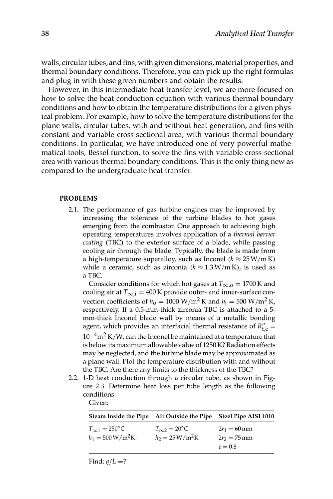
Steam Inside the Pipe Air Outside the Pipe Steel Pipe AISI 1010
T ∞1 = 250 ◦ C
T ∞2 = 20 ◦ C
2r 1 = 60 mm
h 1 = 500 W/m 2 K
h 2 = 25 W/m 2 K
2r 2 = 75 mm
ε = 0.8
Find: q/L =?
Analytical Heat Transfer
walls, circular tubes, and fins, with given dimensions, material properties, and
thermal boundary conditions. Therefore, you can pick up the right formulas
and plug in with these given numbers and obtain the results.
However, in this intermediate heat transfer level, we are more focused on
how to solve the heat conduction equation with various thermal boundary
conditions and how to obtain the temperature distributions for a given physical problem. For example, how to solve the temperature distributions for the
plane walls, circular tubes, with and without heat generation, and fins with
constant and variable cross-sectional area, with various thermal boundary
conditions. In particular, we have introduced one of very powerful mathematical tools, Bessel function, to solve the fins with variable cross-sectional
area with various thermal boundary conditions. This is the only thing new as
compared to the undergraduate heat transfer.
PROBLEMS
2.1. The performance of gas turbine engines may be improved by
increasing the tolerance of the turbine blades to hot gases
emerging from the combustor. One approach to achieving high
operating temperatures involves application of a thermal barrier
coating (TBC) to the exterior surface of a blade, while passing
cooling air through the blade. Typically, the blade is made from
a high-temperature superalloy, such as Inconel (k ≈ 25 W/m K)
while a ceramic, such as zirconia (k ≈ 1.3 W/m K), is used as
a TBC.
Consider conditions for which hot gases at T ∞,o = 1700 K and
cooling air at T ∞,i = 400 K provide outer- and inner-surface convection coefficients of h o = 1000 W/m 2 K and h i = 500 W/m 2 K,
respectively. If a 0.5-mm-thick zirconia TBC is attached to a 5mm-thick Inconel blade wall by means of a metallic bonding
agent, which provides an interfacial thermal resistance of R "" =
t,c
10 −4 m 2 K/W, can the Inconel be maintained at a temperature that
is below its maximum allowable value of 1250 K? Radiation effects
may be neglected, and the turbine blade may be approximated as
a plane wall. Plot the temperature distribution with and without
the TBC. Are there any limits to the thickness of the TBC?
2.2. 1-D heat conduction through a circular tube, as shown in Figure 2.3. Determine heat loss per tube length as the following
conditions:
Given:
Steam Inside the Pipe Air Outside the Pipe Steel Pipe AISI 1010
T ∞1 = 250 ◦ C
T ∞2 = 20 ◦ C
2r 1 = 60 mm
h 1 = 500 W/m 2 K
h 2 = 25 W/m 2 K
2r 2 = 75 mm
ε = 0.8
Find: q/L =?