

39
1-D Steady-State Heat Conduction
2.3. Heat is generated at a rate q ˙ in a long solid cylinder of radius
r o , as shown in Figure 2.6. The cylinder has a thin metal sheath
and is immersed in a liquid at temperature T ∞ . Heat transfer
from the cylinder surface to the liquid can be characterized by
a heat transfer coefficient h. Obtain the steady-state temperature
distributions for the following cases:
a. q ˙ = q ˙ o
�
1 − (r/r 2
o ) .
b. q ˙ = a + b(T
�
− T ∞ ).
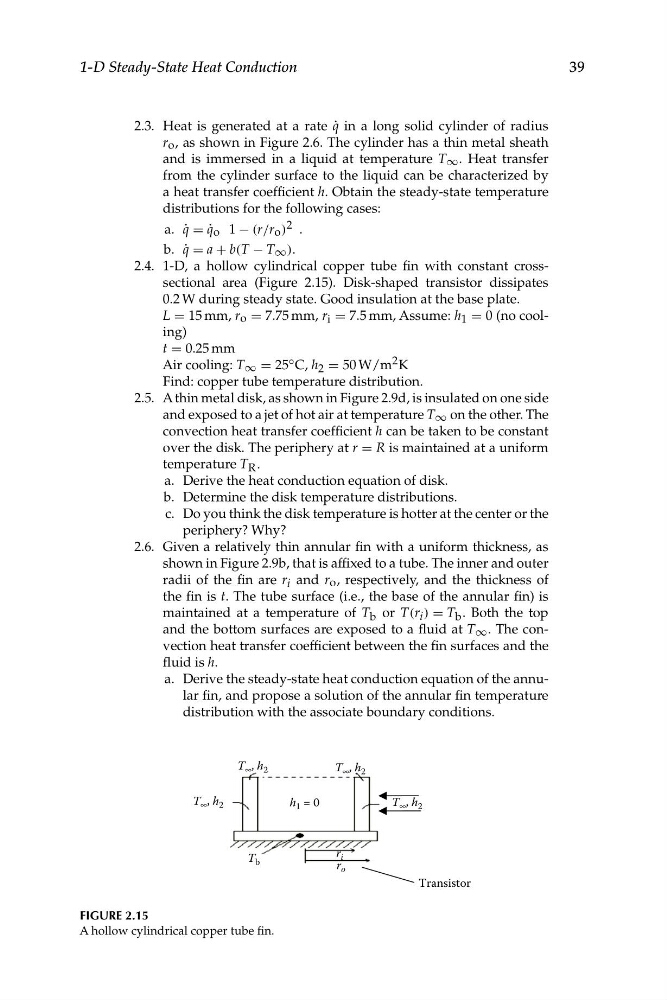
2.4. 1-D, a hollow cylindrical copper tube fin with constant crosssectional area (Figure 2.15). Disk-shaped transistor dissipates
0.2 W during steady state. Good insulation at the base plate.
L = 15 mm, r o = 7.75 mm, r i = 7.5 mm, Assume: h 1 = 0 (no cooling)
t = 0.25 mm
Air cooling: T ∞ = 25 ◦ C, h 2 = 50 W/m 2 K
Find: copper tube temperature distribution.
2.5. A thin metal disk, as shown in Figure 2.9d, is insulated on one side
and exposed to a jet of hot air at temperature T ∞ on the other. The
convection heat transfer coefficient h can be taken to be constant
over the disk. The periphery at r = R is maintained at a uniform
temperature T R .
a. Derive the heat conduction equation of disk.
b. Determine the disk temperature distributions.
c. Do you think the disk temperature is hotter at the center or the
periphery? Why?
2.6. Given a relatively thin annular fin with a uniform thickness, as
shown in Figure 2.9b, that is affixed to a tube. The inner and outer
radii of the fin are r i and r o , respectively, and the thickness of
the fin is t. The tube surface (i.e., the base of the annular fin) is
maintained at a temperature of T b or T(r i ) = T b . Both the top
and the bottom surfaces are exposed to a fluid at T ∞ . The convection heat transfer coefficient between the fin surfaces and the
fluid is h.
a. Derive the steady-state heat conduction equation of the annular fin, and propose a solution of the annular fin temperature
distribution with the associate boundary conditions.
Transistor
T • , h 2
T • , h 2
T • , h 2
T • , h 2
h 1 = 0
T b
r i
r o
FIGURE 2.15
A hollow cylindrical copper tube fin.
1-D Steady-State Heat Conduction
2.3. Heat is generated at a rate q ˙ in a long solid cylinder of radius
r o , as shown in Figure 2.6. The cylinder has a thin metal sheath
and is immersed in a liquid at temperature T ∞ . Heat transfer
from the cylinder surface to the liquid can be characterized by
a heat transfer coefficient h. Obtain the steady-state temperature
distributions for the following cases:
a. q ˙ = q ˙ o
�
1 − (r/r 2
o ) .
b. q ˙ = a + b(T
�
− T ∞ ).
2.4. 1-D, a hollow cylindrical copper tube fin with constant crosssectional area (Figure 2.15). Disk-shaped transistor dissipates
0.2 W during steady state. Good insulation at the base plate.
L = 15 mm, r o = 7.75 mm, r i = 7.5 mm, Assume: h 1 = 0 (no cooling)
t = 0.25 mm
Air cooling: T ∞ = 25 ◦ C, h 2 = 50 W/m 2 K
Find: copper tube temperature distribution.
2.5. A thin metal disk, as shown in Figure 2.9d, is insulated on one side
and exposed to a jet of hot air at temperature T ∞ on the other. The
convection heat transfer coefficient h can be taken to be constant
over the disk. The periphery at r = R is maintained at a uniform
temperature T R .
a. Derive the heat conduction equation of disk.
b. Determine the disk temperature distributions.
c. Do you think the disk temperature is hotter at the center or the
periphery? Why?
2.6. Given a relatively thin annular fin with a uniform thickness, as
shown in Figure 2.9b, that is affixed to a tube. The inner and outer
radii of the fin are r i and r o , respectively, and the thickness of
the fin is t. The tube surface (i.e., the base of the annular fin) is
maintained at a temperature of T b or T(r i ) = T b . Both the top
and the bottom surfaces are exposed to a fluid at T ∞ . The convection heat transfer coefficient between the fin surfaces and the
fluid is h.
a. Derive the steady-state heat conduction equation of the annular fin, and propose a solution of the annular fin temperature
distribution with the associate boundary conditions.
Transistor
T • , h 2
T • , h 2
T • , h 2
T • , h 2
h 1 = 0
T b
r i
r o
FIGURE 2.15
A hollow cylindrical copper tube fin.