

248
9
Dielectric constant and transmission losses at various frequencies are measured using a vector network analyzer (VNA). A
full two-port calibration is carried out using the TRL (Thru,
Reflect, Line) calibration method using calibration standards.
The accuracy of the waveguide set-up needs to be in the range
of 1%. The verification of the waveguide set-up is carried out
with known standards. A typical sample size is
22.86 × 10.16 × 3.0 mm 3 . A micrometre (least count 0.01 mm)
is used for the measurement of thickness, which is carried out
on various locations (minimum 5) of the prepared sample in
order to ensure the accuracy and uniformity of the thickness.
2. Loss Tangent—An electromagnetic wave has two components:
electrical and magnetic. When an electrical field is applied to a
dielectric material, electrical energy is absorbed in the polarization, such as electronic polarization, ionic polarization,
dipole orientation, and space charge polarization. This polarization results in a loss of energy. Maximum loss of energy
occurs when 63% of the total polarization process is completed
and resonance occurs. This loss of energy is measured in the
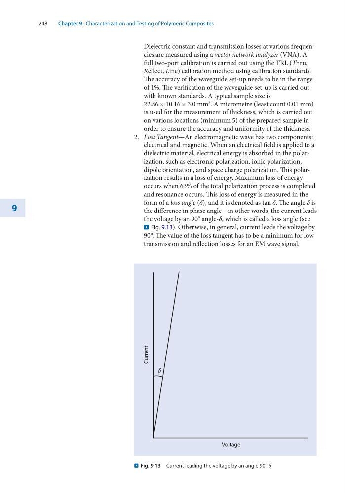
form of a loss angle (δ), and it is denoted as tan δ. The angle δ is
the difference in phase angle—in other words, the current leads
the voltage by an 90° angle-δ, which is called a loss angle (see
. Fig. 9.13). Otherwise, in general, current leads the voltage by
90°. The value of the loss tangent has to be a minimum for low
transmission and reflection losses for an EM wave signal.
Voltage
d
Current
. Fig. 9.13 Current leading the voltage by an angle 90°-δ
Chapter 9 · Characterization and Testing of Polymeric Composites
9
Dielectric constant and transmission losses at various frequencies are measured using a vector network analyzer (VNA). A
full two-port calibration is carried out using the TRL (Thru,
Reflect, Line) calibration method using calibration standards.
The accuracy of the waveguide set-up needs to be in the range
of 1%. The verification of the waveguide set-up is carried out
with known standards. A typical sample size is
22.86 × 10.16 × 3.0 mm 3 . A micrometre (least count 0.01 mm)
is used for the measurement of thickness, which is carried out
on various locations (minimum 5) of the prepared sample in
order to ensure the accuracy and uniformity of the thickness.
2. Loss Tangent—An electromagnetic wave has two components:
electrical and magnetic. When an electrical field is applied to a
dielectric material, electrical energy is absorbed in the polarization, such as electronic polarization, ionic polarization,
dipole orientation, and space charge polarization. This polarization results in a loss of energy. Maximum loss of energy
occurs when 63% of the total polarization process is completed
and resonance occurs. This loss of energy is measured in the
form of a loss angle (δ), and it is denoted as tan δ. The angle δ is
the difference in phase angle—in other words, the current leads
the voltage by an 90° angle-δ, which is called a loss angle (see
. Fig. 9.13). Otherwise, in general, current leads the voltage by
90°. The value of the loss tangent has to be a minimum for low
transmission and reflection losses for an EM wave signal.
Voltage
d
Current
. Fig. 9.13 Current leading the voltage by an angle 90°-δ
Chapter 9 · Characterization and Testing of Polymeric Composites