

1 3
Topics in Current Chemistry (2019) 377:22
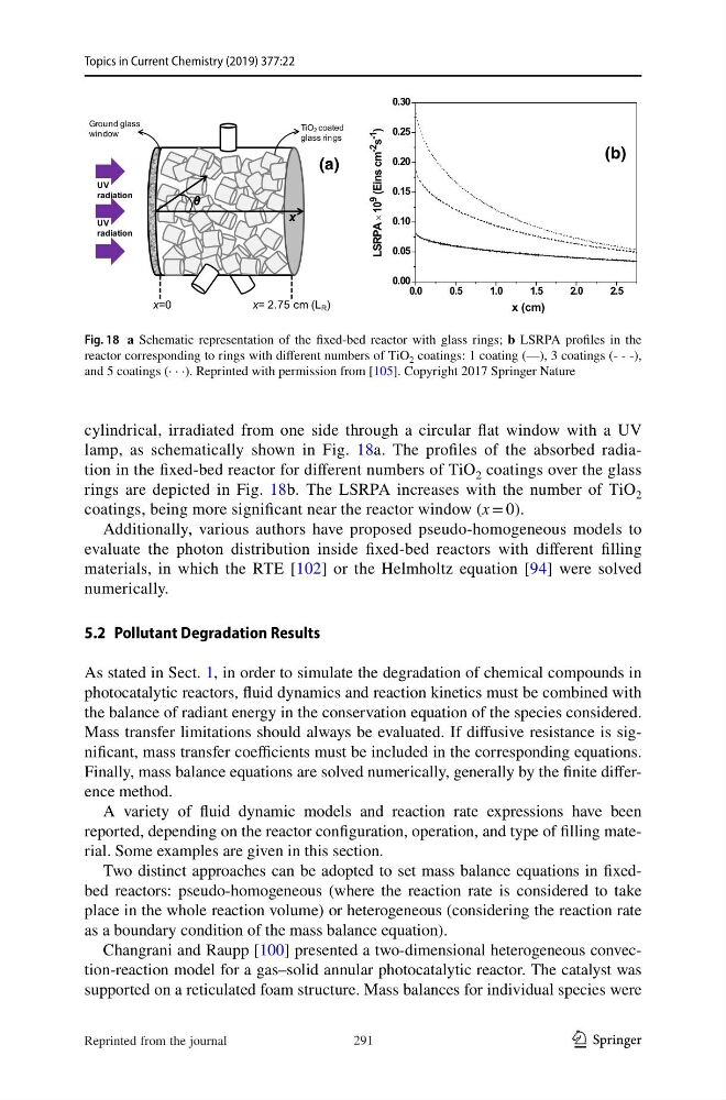
cylindrical, irradiated from one side through a circular flat window with a UV
lamp, as schematically shown in Fig. 18a. The profiles of the absorbed radiation in the fixed-bed reactor for different numbers of TiO 2 coatings over the glass
rings are depicted in Fig. 18b. The LSRPA increases with the number of TiO 2
coatings, being more significant near the reactor window (x = 0).
Additionally, various authors have proposed pseudo-homogeneous models to
evaluate the photon distribution inside fixed-bed reactors with different filling
materials, in which the RTE [102] or the Helmholtz equation [94] were solved
numerically.
5.2 Pollutant Degradation Results
As stated in Sect. 1, in order to simulate the degradation of chemical compounds in
photocatalytic reactors, fluid dynamics and reaction kinetics must be combined with
the balance of radiant energy in the conservation equation of the species considered.
Mass transfer limitations should always be evaluated. If diffusive resistance is significant, mass transfer coefficients must be included in the corresponding equations.
Finally, mass balance equations are solved numerically, generally by the finite difference method.
A variety of fluid dynamic models and reaction rate expressions have been
reported, depending on the reactor configuration, operation, and type of filling material. Some examples are given in this section.
Two distinct approaches can be adopted to set mass balance equations in fixedbed reactors: pseudo-homogeneous (where the reaction rate is considered to take
place in the whole reaction volume) or heterogeneous (considering the reaction rate
as a boundary condition of the mass balance equation).
Changrani and Raupp [100] presented a two-dimensional heterogeneous convection-reaction model for a gas–solid annular photocatalytic reactor. The catalyst was
supported on a reticulated foam structure. Mass balances for individual species were
x=0
x= 2.75 cm (L R )
x
θ
TiO2 coated
glass rings
Ground glass
window
UV
radiation
UV
radiation
0.0
0 .5
1.0
1 .5
2.0
2 .5
0.00
0.05
0.10
0.15
0.20
0.25
0.30
LSRPA ×
10 9
(Eins cm -2
s -1
)
x (cm)
(a)
(b)
Fig. 18 a Schematic representation of the fixed-bed reactor with glass rings; b LSRPA profiles in the
reactor corresponding to rings with different numbers of TiO 2 coatings: 1 coating (—), 3 coatings (- - -),
and 5 coatings (· · ·). Reprinted with permission from [105]. Copyright 2017 Springer Nature
291
Reprinted from the journal
Topics in Current Chemistry (2019) 377:22
cylindrical, irradiated from one side through a circular flat window with a UV
lamp, as schematically shown in Fig. 18a. The profiles of the absorbed radiation in the fixed-bed reactor for different numbers of TiO 2 coatings over the glass
rings are depicted in Fig. 18b. The LSRPA increases with the number of TiO 2
coatings, being more significant near the reactor window (x = 0).
Additionally, various authors have proposed pseudo-homogeneous models to
evaluate the photon distribution inside fixed-bed reactors with different filling
materials, in which the RTE [102] or the Helmholtz equation [94] were solved
numerically.
5.2 Pollutant Degradation Results
As stated in Sect. 1, in order to simulate the degradation of chemical compounds in
photocatalytic reactors, fluid dynamics and reaction kinetics must be combined with
the balance of radiant energy in the conservation equation of the species considered.
Mass transfer limitations should always be evaluated. If diffusive resistance is significant, mass transfer coefficients must be included in the corresponding equations.
Finally, mass balance equations are solved numerically, generally by the finite difference method.
A variety of fluid dynamic models and reaction rate expressions have been
reported, depending on the reactor configuration, operation, and type of filling material. Some examples are given in this section.
Two distinct approaches can be adopted to set mass balance equations in fixedbed reactors: pseudo-homogeneous (where the reaction rate is considered to take
place in the whole reaction volume) or heterogeneous (considering the reaction rate
as a boundary condition of the mass balance equation).
Changrani and Raupp [100] presented a two-dimensional heterogeneous convection-reaction model for a gas–solid annular photocatalytic reactor. The catalyst was
supported on a reticulated foam structure. Mass balances for individual species were
x=0
x= 2.75 cm (L R )
x
θ
TiO2 coated
glass rings
Ground glass
window
UV
radiation
UV
radiation
0.0
0 .5
1.0
1 .5
2.0
2 .5
0.00
0.05
0.10
0.15
0.20
0.25
0.30
LSRPA ×
10 9
(Eins cm -2
s -1
)
x (cm)
(a)
(b)
Fig. 18 a Schematic representation of the fixed-bed reactor with glass rings; b LSRPA profiles in the
reactor corresponding to rings with different numbers of TiO 2 coatings: 1 coating (—), 3 coatings (- - -),
and 5 coatings (· · ·). Reprinted with permission from [105]. Copyright 2017 Springer Nature
291
Reprinted from the journal