

416
32 On Boundary Value Problems of Inelastic Body Mechanics
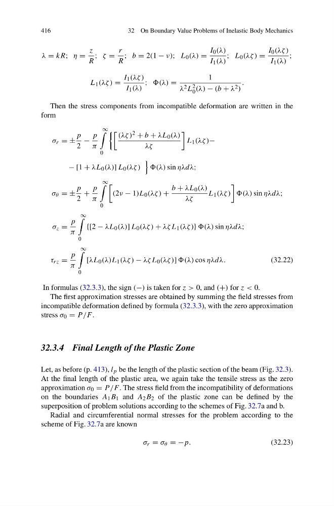
λ = kR; η =
z
R
; ζ =
r
R
; b = 2(1 − ν); L 0 (λ) =
I 0 (λ)
I 1 (λ)
; L 0 (λζ ) =
I 0 (λζ )
I 1 (λ)
;
L 1 (λζ ) =
I 1 (λζ )
I 1 (λ)
; (λ) =
1
λ 2 L 2
0 (λ) − (b + λ 2 )
.
Then the stress components from incompatible deformation are written in the
form
σ r = ±
p
2
−
p
π
∞
0
(λζ ) 2 + b + λL 0 (λ)
λζ
L 1 (λζ )−
− [1 + λL 0 (λ)] L 0 (λζ )
(λ) sin ηλdλ;
σ θ = ±
p
2
+
p
π
∞
0
(2ν − 1)L 0 (λζ ) +
b + λL 0 (λ)
λζ
L 1 (λζ )
(λ) sin ηλdλ;
σ z =
p
π
∞
0
{[2 − λL 0 (λ)] L 0 (λζ ) + λζ L 1 (λζ )} (λ) sin ηλdλ;
τ rz =
p
π
∞
0
[λL 0 (λ)L 1 (λζ ) − λζ L 0 (λζ )] (λ) cos ηλdλ.
(32.22)
In formulas (32.3.3), the sign (−) is taken for z > 0, and (+) for z < 0.
The first approximation stresses are obtained by summing the field stresses from
incompatible deformation defined by formula (32.3.3), with the zero approximation
stress σ 0 = P /F .
32.3.4 Final Length of the Plastic Zone
Let, as before (p. 413), l p be the length of the plastic section of the beam (Fig. 32.3).
At the final length of the plastic area, we again take the tensile stress as the zero
approximation σ 0 = P /F . The stress field from the incompatibility of deformations
on the boundaries A 1 B 1 and A 2 B 2 of the plastic zone can be defined by the
superposition of problem solutions according to the schemes of Fig. 32.7a and b.
Radial and circumferential normal stresses for the problem according to the
scheme of Fig. 32.7a are known
σ r = σ θ = −p.
(32.23)
32 On Boundary Value Problems of Inelastic Body Mechanics
λ = kR; η =
z
R
; ζ =
r
R
; b = 2(1 − ν); L 0 (λ) =
I 0 (λ)
I 1 (λ)
; L 0 (λζ ) =
I 0 (λζ )
I 1 (λ)
;
L 1 (λζ ) =
I 1 (λζ )
I 1 (λ)
; (λ) =
1
λ 2 L 2
0 (λ) − (b + λ 2 )
.
Then the stress components from incompatible deformation are written in the
form
σ r = ±
p
2
−
p
π
∞
0
(λζ ) 2 + b + λL 0 (λ)
λζ
L 1 (λζ )−
− [1 + λL 0 (λ)] L 0 (λζ )
(λ) sin ηλdλ;
σ θ = ±
p
2
+
p
π
∞
0
(2ν − 1)L 0 (λζ ) +
b + λL 0 (λ)
λζ
L 1 (λζ )
(λ) sin ηλdλ;
σ z =
p
π
∞
0
{[2 − λL 0 (λ)] L 0 (λζ ) + λζ L 1 (λζ )} (λ) sin ηλdλ;
τ rz =
p
π
∞
0
[λL 0 (λ)L 1 (λζ ) − λζ L 0 (λζ )] (λ) cos ηλdλ.
(32.22)
In formulas (32.3.3), the sign (−) is taken for z > 0, and (+) for z < 0.
The first approximation stresses are obtained by summing the field stresses from
incompatible deformation defined by formula (32.3.3), with the zero approximation
stress σ 0 = P /F .
32.3.4 Final Length of the Plastic Zone
Let, as before (p. 413), l p be the length of the plastic section of the beam (Fig. 32.3).
At the final length of the plastic area, we again take the tensile stress as the zero
approximation σ 0 = P /F . The stress field from the incompatibility of deformations
on the boundaries A 1 B 1 and A 2 B 2 of the plastic zone can be defined by the
superposition of problem solutions according to the schemes of Fig. 32.7a and b.
Radial and circumferential normal stresses for the problem according to the
scheme of Fig. 32.7a are known
σ r = σ θ = −p.
(32.23)