

336
24 Specimen Elongation with Yield Drop
one end of the working part of the specimen increases to the other end. Then the
element x will be located near the end of the specimen with the lower material
strength. The origin of the plastic strain in the element is accompanied by the drop
of stress in this element from the upper yield stress σ y to the initial shear resistance
σ 0 and then by its rise as per the law (24.1).
This stress drop is of impulse nature, but the diagram shows the rise “blurred”
due to the inertia of mobile parts of the loading device. As a result of the stress
rise, an elastic wave of unloading will propagate through the specimen at the rate
c 0 of sound propagation in the material. Let us use A − A (Fig. 24.2) to designate
the boundary of the plastically deformed element x and the elastic part of the
specimen. Assume that after t = 0, there is a moment in time when the stress drops
in the element from σ y to σ 0 . As a result of the unloading elastic wave, the crosssection A − A will move for the time dt to the distance
du =
σ y − σ (t)
E
c 0 dt,
where E is the Young modulus.
For the time t, the elastic wave front will reach the cross-section B −B (Fig. 24.2)
distanced from A − A to the distance c 0 t, and the displacement of the section A − A
will be
u(t) =
c 0
E
t
0
[σ y − σ (ξ)]dξ,
t <
2l
c 0
,
(24.3)
whereas l is the length of the specimen working part. The displacement of the
section A − A will cause the plastic strain of the element x:
ε =
u(t)
x
=
c 0
E · x
t
0
[σ y − σ (ξ)]dξ.
(24.4)
Let us make an assumption that in the case of uniaxial loading, the link between
stress σ (t), plastic strain ε, and its rate ˙
ε can be expressed by the formula:
σ (t) = k 0 + k 1 ε(t) + k 2 ˙
ε(t), (k 0 , k 1 , k 2 − const).
(24.5)
By substituting strain (24.4) and its derivative into this formula, we obtain the
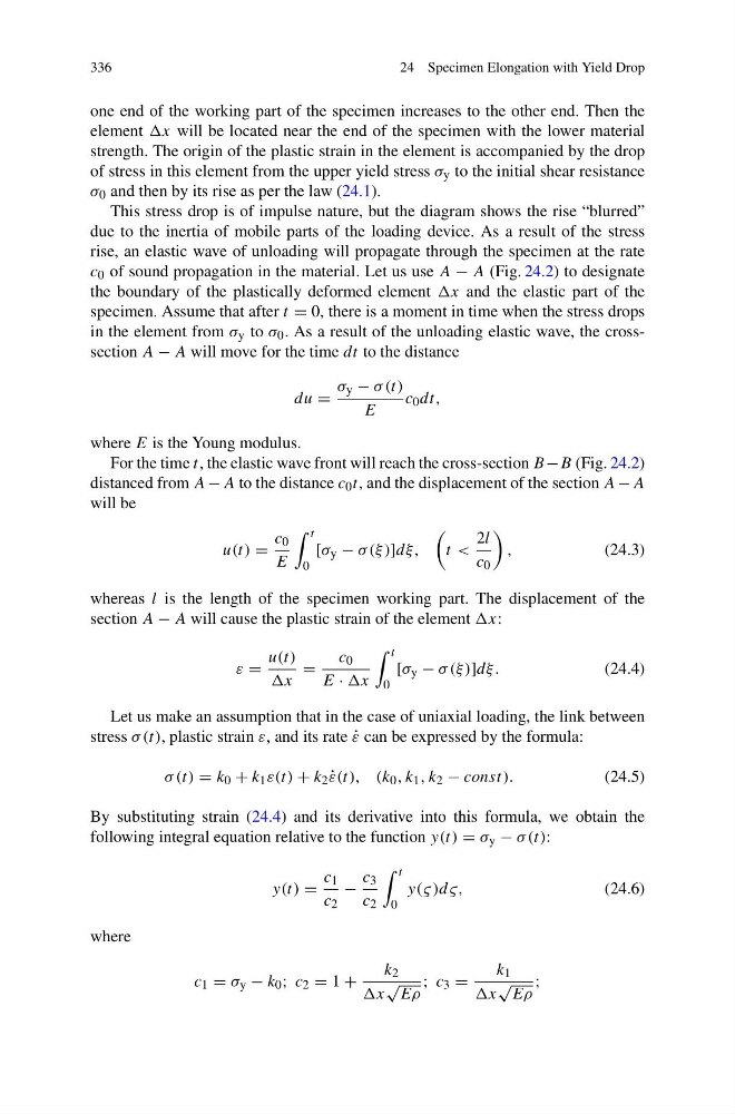
following integral equation relative to the function y(t) = σ y − σ (t):
y(t) =
c 1
c 2
−
c 3
c 2
t
0
y(ς)dς,
(24.6)
where
c 1 = σ y − k 0 ; c 2 = 1 +
k 2
x
√
Eρ
; c 3 =
k 1
x
√
Eρ
;
24 Specimen Elongation with Yield Drop
one end of the working part of the specimen increases to the other end. Then the
element x will be located near the end of the specimen with the lower material
strength. The origin of the plastic strain in the element is accompanied by the drop
of stress in this element from the upper yield stress σ y to the initial shear resistance
σ 0 and then by its rise as per the law (24.1).
This stress drop is of impulse nature, but the diagram shows the rise “blurred”
due to the inertia of mobile parts of the loading device. As a result of the stress
rise, an elastic wave of unloading will propagate through the specimen at the rate
c 0 of sound propagation in the material. Let us use A − A (Fig. 24.2) to designate
the boundary of the plastically deformed element x and the elastic part of the
specimen. Assume that after t = 0, there is a moment in time when the stress drops
in the element from σ y to σ 0 . As a result of the unloading elastic wave, the crosssection A − A will move for the time dt to the distance
du =
σ y − σ (t)
E
c 0 dt,
where E is the Young modulus.
For the time t, the elastic wave front will reach the cross-section B −B (Fig. 24.2)
distanced from A − A to the distance c 0 t, and the displacement of the section A − A
will be
u(t) =
c 0
E
t
0
[σ y − σ (ξ)]dξ,
t <
2l
c 0
,
(24.3)
whereas l is the length of the specimen working part. The displacement of the
section A − A will cause the plastic strain of the element x:
ε =
u(t)
x
=
c 0
E · x
t
0
[σ y − σ (ξ)]dξ.
(24.4)
Let us make an assumption that in the case of uniaxial loading, the link between
stress σ (t), plastic strain ε, and its rate ˙
ε can be expressed by the formula:
σ (t) = k 0 + k 1 ε(t) + k 2 ˙
ε(t), (k 0 , k 1 , k 2 − const).
(24.5)
By substituting strain (24.4) and its derivative into this formula, we obtain the
following integral equation relative to the function y(t) = σ y − σ (t):
y(t) =
c 1
c 2
−
c 3
c 2
t
0
y(ς)dς,
(24.6)
where
c 1 = σ y − k 0 ; c 2 = 1 +
k 2
x
√
Eρ
; c 3 =
k 1
x
√
Eρ
;