

16.4 Symmetric Strain of a Cylindrical Tube
235
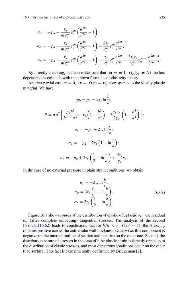
σ r = −p a +
τ s
mγ m
s
γ
m
a
a 2m
r 2m − 1
;
σ ϕ = −p a +
τ s
mγ m
s
γ
m
a
a 2m
r 2m − 1
+
2τ s
γ m
s
γ
m
a
a 2m
r 2m ;
σ z = −p a +
τ s
mγ m
s
γ
m
a
a 2m
r 2m − 1
+
τ s
γ m
s
γ
m
a
a 2m
r 2m +
3τ s ε z
γ m
s
γ
m−1
a
a 2m−2
b 2m−2 .
By directly checking, one can make sure that for m = 1, (τ s /γ s = G) the last
dependencies coincide with the known formulas of elasticity theory.
Another partial case m = 0, (τ = f (γ ) = τ s ) corresponds to the ideally plastic
material. We have
p b − p a = 2τ s ln
b
a
;
P = πa
2
p b b 2
b 2 − a 2 − τ s
1 −
b 2
a 2
− 3
τ s ε z
2γ a
1 −
b 4
a 4
;
σ r = −p a + 2τ s ln
r
a
;
σ ϕ = −p a + 2τ s
1 + ln
r
a
;
σ z = −p a + 2τ s
1
2
+ ln
r
a
+
3τ s
γ a
ε z .
In the case of no external pressure in plain strain conditions, we obtain
σ r = −2τ s ln
b
r
,
σ ϕ = 2τ s
1 − ln
b
r
,
σ z = 2τ s
1
2
− ln
b
r
.
(16.62)
Figure 16.7 shows epures of the distribution of elastic σ
y
ϕ , plastic σ ϕ , and residual
˜
σ ϕ (after complete unloading) tangential stresses. The analysis of the second
formula (16.62) leads to conclusions that for b/a < e, (ln e = 1), the stress σ ϕ
remains positive across the entire tube wall thickness. Otherwise, this component is
negative on the internal outline of section and positive on the outer one. Second, the
distribution nature of stresses in the case of tube plastic strain is directly opposite to
the distribution of elastic stresses, and most dangerous conditions occur on the outer
tube surface. This fact is experimentally confirmed by Bridgeman [2].
235
σ r = −p a +
τ s
mγ m
s
γ
m
a
a 2m
r 2m − 1
;
σ ϕ = −p a +
τ s
mγ m
s
γ
m
a
a 2m
r 2m − 1
+
2τ s
γ m
s
γ
m
a
a 2m
r 2m ;
σ z = −p a +
τ s
mγ m
s
γ
m
a
a 2m
r 2m − 1
+
τ s
γ m
s
γ
m
a
a 2m
r 2m +
3τ s ε z
γ m
s
γ
m−1
a
a 2m−2
b 2m−2 .
By directly checking, one can make sure that for m = 1, (τ s /γ s = G) the last
dependencies coincide with the known formulas of elasticity theory.
Another partial case m = 0, (τ = f (γ ) = τ s ) corresponds to the ideally plastic
material. We have
p b − p a = 2τ s ln
b
a
;
P = πa
2
p b b 2
b 2 − a 2 − τ s
1 −
b 2
a 2
− 3
τ s ε z
2γ a
1 −
b 4
a 4
;
σ r = −p a + 2τ s ln
r
a
;
σ ϕ = −p a + 2τ s
1 + ln
r
a
;
σ z = −p a + 2τ s
1
2
+ ln
r
a
+
3τ s
γ a
ε z .
In the case of no external pressure in plain strain conditions, we obtain
σ r = −2τ s ln
b
r
,
σ ϕ = 2τ s
1 − ln
b
r
,
σ z = 2τ s
1
2
− ln
b
r
.
(16.62)
Figure 16.7 shows epures of the distribution of elastic σ
y
ϕ , plastic σ ϕ , and residual
˜
σ ϕ (after complete unloading) tangential stresses. The analysis of the second
formula (16.62) leads to conclusions that for b/a < e, (ln e = 1), the stress σ ϕ
remains positive across the entire tube wall thickness. Otherwise, this component is
negative on the internal outline of section and positive on the outer one. Second, the
distribution nature of stresses in the case of tube plastic strain is directly opposite to
the distribution of elastic stresses, and most dangerous conditions occur on the outer
tube surface. This fact is experimentally confirmed by Bridgeman [2].