

13.6 Stress Diagrams and Their Idealization
177
where η is similar to the angle defined for the strain deviator, and I
2 , I
3 are
invariants of the strain deviator.
According to Definition 2, if the angles and η are equal, and the principal
axes coincide, the stress deviator and strain deviator are similar. According to
Definition 1, the director tensors of these deviators are equal. For similar deviators,
Lode and Nadai introduced [4] invariants
μ σ = 2
σ 2 − σ 3
σ 1 − σ 3
− 1, μ ε = 2
ε 2 − ε 3
ε 1 − ε 3
− 1.
(13.44)
Invariants defined by formulas (13.44) are referred to as Lode and Nadai parameters.
It can be shown that they can be expressed through the second and third invariants
of the respective deviators and the areas of changes in their values are defined by
the formulas
− 1 μ σ 1, μ ε 1.
(13.45)
13.6 Stress Diagrams and Their Idealization
In the mechanics of non-elastic deformations, many positions are obtained as a result
of summarizing observations in the case of uniaxial elongation of material samples.
Therefore, it is reasonable to return to the analysis of stress diagrams σ ∼ ε.
Previously, we talked of the stress diagram (Fig. 1.3) for a material with the yield
area. However, not all plastic materials find the yield area on the stress diagram. In
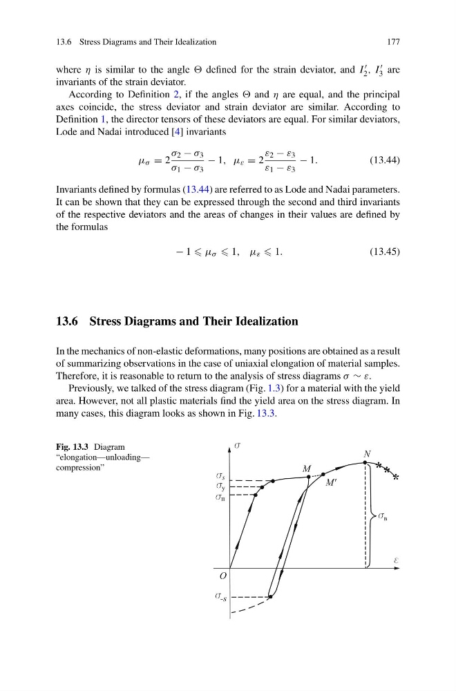
many cases, this diagram looks as shown in Fig. 13.3.
Fig. 13.3 Diagram
“elongation—unloading—
compression”
177
where η is similar to the angle defined for the strain deviator, and I
2 , I
3 are
invariants of the strain deviator.
According to Definition 2, if the angles and η are equal, and the principal
axes coincide, the stress deviator and strain deviator are similar. According to
Definition 1, the director tensors of these deviators are equal. For similar deviators,
Lode and Nadai introduced [4] invariants
μ σ = 2
σ 2 − σ 3
σ 1 − σ 3
− 1, μ ε = 2
ε 2 − ε 3
ε 1 − ε 3
− 1.
(13.44)
Invariants defined by formulas (13.44) are referred to as Lode and Nadai parameters.
It can be shown that they can be expressed through the second and third invariants
of the respective deviators and the areas of changes in their values are defined by
the formulas
− 1 μ σ 1, μ ε 1.
(13.45)
13.6 Stress Diagrams and Their Idealization
In the mechanics of non-elastic deformations, many positions are obtained as a result
of summarizing observations in the case of uniaxial elongation of material samples.
Therefore, it is reasonable to return to the analysis of stress diagrams σ ∼ ε.
Previously, we talked of the stress diagram (Fig. 1.3) for a material with the yield
area. However, not all plastic materials find the yield area on the stress diagram. In
many cases, this diagram looks as shown in Fig. 13.3.
Fig. 13.3 Diagram
“elongation—unloading—
compression”