

28
A. V. Babakov
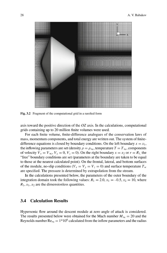
Fig. 3.2 Fragment of the computational grid in a rarefied form
axis toward the positive direction of the OZ axis. In the calculations, computational
grids containing up to 20 million finite volumes were used.
For each finite volume, finite-difference analogues of the conservation laws of
mass, momentum components, and total energy are written out. The system of finitedifference equations is closed by boundary conditions. On the left boundary x = x 1 ,
the inflowing parameters are set (density ρ = ρ ∞ , temperature T = T ∞ , components
of velocity V x = V ∞ , V y = 0, V z = 0). On the right boundary x = x 2 or r = R 1, the
“free” boundary conditions are set (parameters at the boundary are taken to be equal
to those at the nearest calculated point). On the frontal, lateral, and bottom surfaces
of the module, no-slip conditions (V x = V y = V z = 0) and surface temperature T w
are specified. The pressure is determined by extrapolation from the stream.
In the calculations presented below, the parameters of the outer boundary of the
integration domain took the following values: R 1 = 2.0, x 1 = –0.5, x 2 = 10, where
R 1 , x 1 , x 2 are the dimensionless quantities.
3.4 Calculation Results
Hypersonic flow around the descent module at zero angle of attack is considered.
The results presented below were obtained for the Mach number M ∞ = 20 and the
Reynolds number Re ∞ = 1*10
6 calculated from the inflow parameters and the radius
A. V. Babakov
Fig. 3.2 Fragment of the computational grid in a rarefied form
axis toward the positive direction of the OZ axis. In the calculations, computational
grids containing up to 20 million finite volumes were used.
For each finite volume, finite-difference analogues of the conservation laws of
mass, momentum components, and total energy are written out. The system of finitedifference equations is closed by boundary conditions. On the left boundary x = x 1 ,
the inflowing parameters are set (density ρ = ρ ∞ , temperature T = T ∞ , components
of velocity V x = V ∞ , V y = 0, V z = 0). On the right boundary x = x 2 or r = R 1, the
“free” boundary conditions are set (parameters at the boundary are taken to be equal
to those at the nearest calculated point). On the frontal, lateral, and bottom surfaces
of the module, no-slip conditions (V x = V y = V z = 0) and surface temperature T w
are specified. The pressure is determined by extrapolation from the stream.
In the calculations presented below, the parameters of the outer boundary of the
integration domain took the following values: R 1 = 2.0, x 1 = –0.5, x 2 = 10, where
R 1 , x 1 , x 2 are the dimensionless quantities.
3.4 Calculation Results
Hypersonic flow around the descent module at zero angle of attack is considered.
The results presented below were obtained for the Mach number M ∞ = 20 and the
Reynolds number Re ∞ = 1*10
6 calculated from the inflow parameters and the radius