

3 Numerical Simulation of Flow Structure Near Descent …
29
of the mid-section. Ratio of specific heat capacities of gas γ is taken equal to 1.335,
corresponding to the atmosphere of the Mars. The surface temperature T w of the
apparatus was assumed to be 0.05 of the inflow adiabatic stagnation temperature.
In what follows, we will use the gas-dynamic variables in dimensionless form,
namely the density ρ and temperature T will be related to the corresponding inflow
parameters ρ ∞ , T ∞ , the velocity will be related to the inflow velocity V ∞ , and the
pressure p to ρ ∞ V
2
∞ and time t to R 0 /V ∞. The flow velocity V ∞ is directed along the
positive direction of the OX axis.
As mentioned above, particular attention during the numerical calculations is paid
to the study of flow properties near the lateral and bottom surfaces of the descent
module. When integrated over time, the numerical solution acquires a non-stationary
character. The flow near the lateral surface and in the near wake has a vortex nonstationary nature.
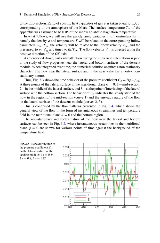
Thus, Fig. 3.3 shows the time behavior of the pressure coefficient C p = 2(p – p ∞ )
at three points of the lateral surface in the meridional plane ϕ = 0: 1—mid-section,
2—in the middle of the lateral surface, and 3—at the point of interfacing of the lateral
surface with the bottom section. The behavior of C p indicates the steady state of the
flow in the region of the mid-section (curve 1) and the unsteady nature of the flow
on the lateral surface of the descent module (curves 2, 3).
This is confirmed by the flow patterns presented in Fig. 3.4, which shows the
general view of the flow in the form of instantaneous streamlines and temperature
field in the meridional plane ϕ = 0 and the bottom region.
The non-stationary and vortex nature of the flow near the lateral and bottom
surfaces can be seen in Fig. 3.5, where instantaneous streamlines in the meridional
plane ϕ = 0 are shown for various points of time against the background of the
temperature field.
Fig. 3.3 Behavior in time of
the pressure coefficient C p
on the lateral surface of the
landing module: 1 x = 0.34,
2 x = 0.8, 3 x = 1.22
29
of the mid-section. Ratio of specific heat capacities of gas γ is taken equal to 1.335,
corresponding to the atmosphere of the Mars. The surface temperature T w of the
apparatus was assumed to be 0.05 of the inflow adiabatic stagnation temperature.
In what follows, we will use the gas-dynamic variables in dimensionless form,
namely the density ρ and temperature T will be related to the corresponding inflow
parameters ρ ∞ , T ∞ , the velocity will be related to the inflow velocity V ∞ , and the
pressure p to ρ ∞ V
2
∞ and time t to R 0 /V ∞. The flow velocity V ∞ is directed along the
positive direction of the OX axis.
As mentioned above, particular attention during the numerical calculations is paid
to the study of flow properties near the lateral and bottom surfaces of the descent
module. When integrated over time, the numerical solution acquires a non-stationary
character. The flow near the lateral surface and in the near wake has a vortex nonstationary nature.
Thus, Fig. 3.3 shows the time behavior of the pressure coefficient C p = 2(p – p ∞ )
at three points of the lateral surface in the meridional plane ϕ = 0: 1—mid-section,
2—in the middle of the lateral surface, and 3—at the point of interfacing of the lateral
surface with the bottom section. The behavior of C p indicates the steady state of the
flow in the region of the mid-section (curve 1) and the unsteady nature of the flow
on the lateral surface of the descent module (curves 2, 3).
This is confirmed by the flow patterns presented in Fig. 3.4, which shows the
general view of the flow in the form of instantaneous streamlines and temperature
field in the meridional plane ϕ = 0 and the bottom region.
The non-stationary and vortex nature of the flow near the lateral and bottom
surfaces can be seen in Fig. 3.5, where instantaneous streamlines in the meridional
plane ϕ = 0 are shown for various points of time against the background of the
temperature field.
Fig. 3.3 Behavior in time of
the pressure coefficient C p
on the lateral surface of the
landing module: 1 x = 0.34,
2 x = 0.8, 3 x = 1.22